Techniques for placing medical leads for electrical stimulation of nerve tissue

Active Publication Date: 2017-02-21
MEDTRONIC INC
View PDF120 Cites 140 Cited by
  • Summary
  • Abstract
  • Description
  • Claims
  • Application Information

AI Technical Summary

Benefits of technology

[0007]In another example, a method includes deploying a delivery catheter through a lumen of a blood vessel to a location proximate a target nerve tissue site outside the blood vessel. A location of

Problems solved by technology

Cuff electrodes have some disadvantages, however, including, that such electrodes require relatively invasive techniques for placing them within a patient.
Additionally, cuff

Method used


Image

  • Techniques for placing medical leads for electrical stimulation of nerve tissue
  • Techniques for placing medical leads for electrical stimulation of nerve tissue
  • Techniques for placing medical leads for electrical stimulation of nerve tissue

Examples


Embodiment Construction

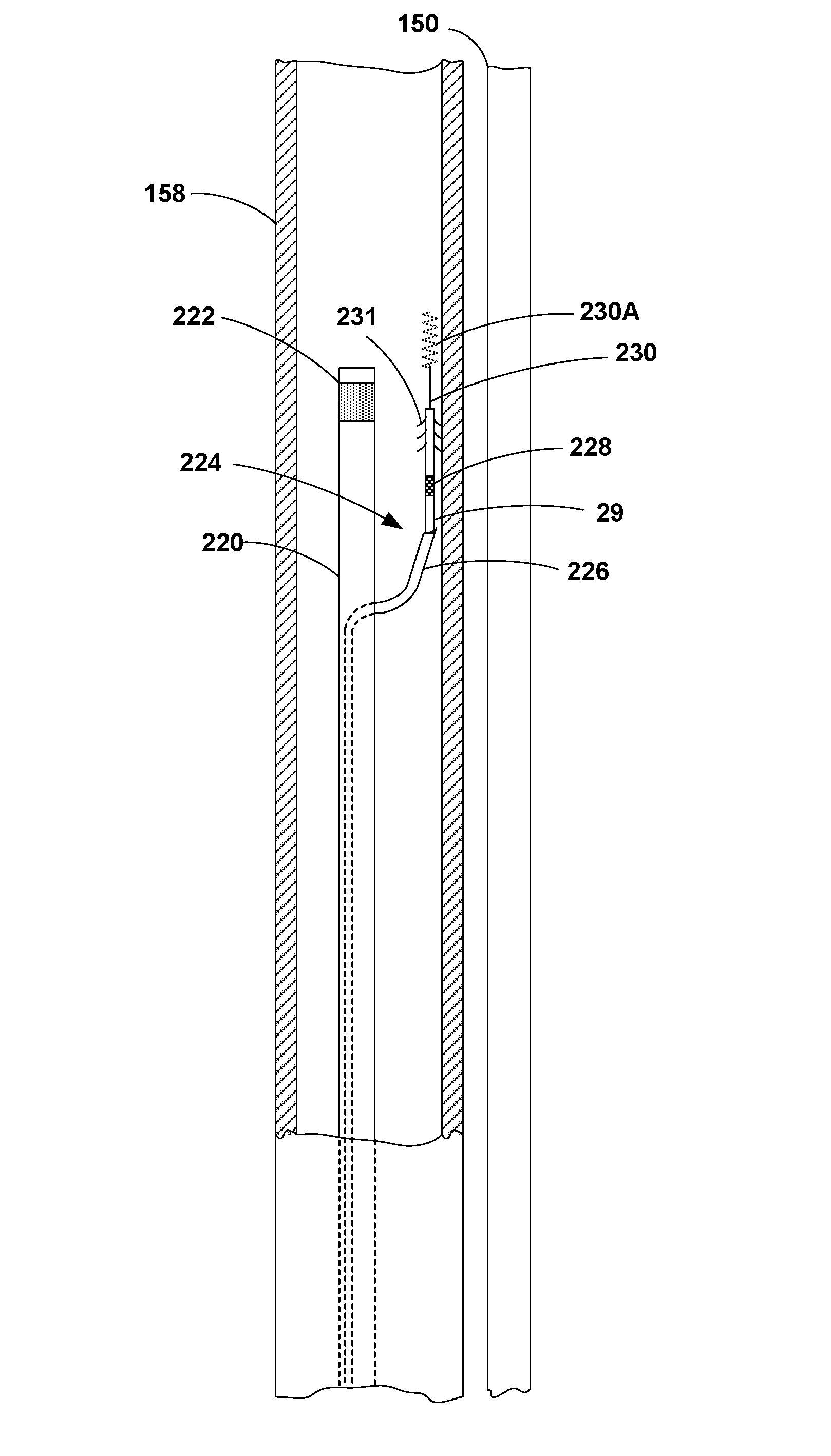
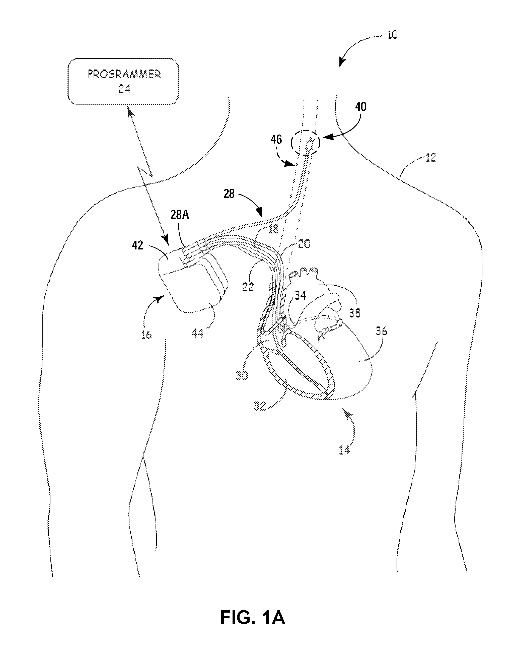
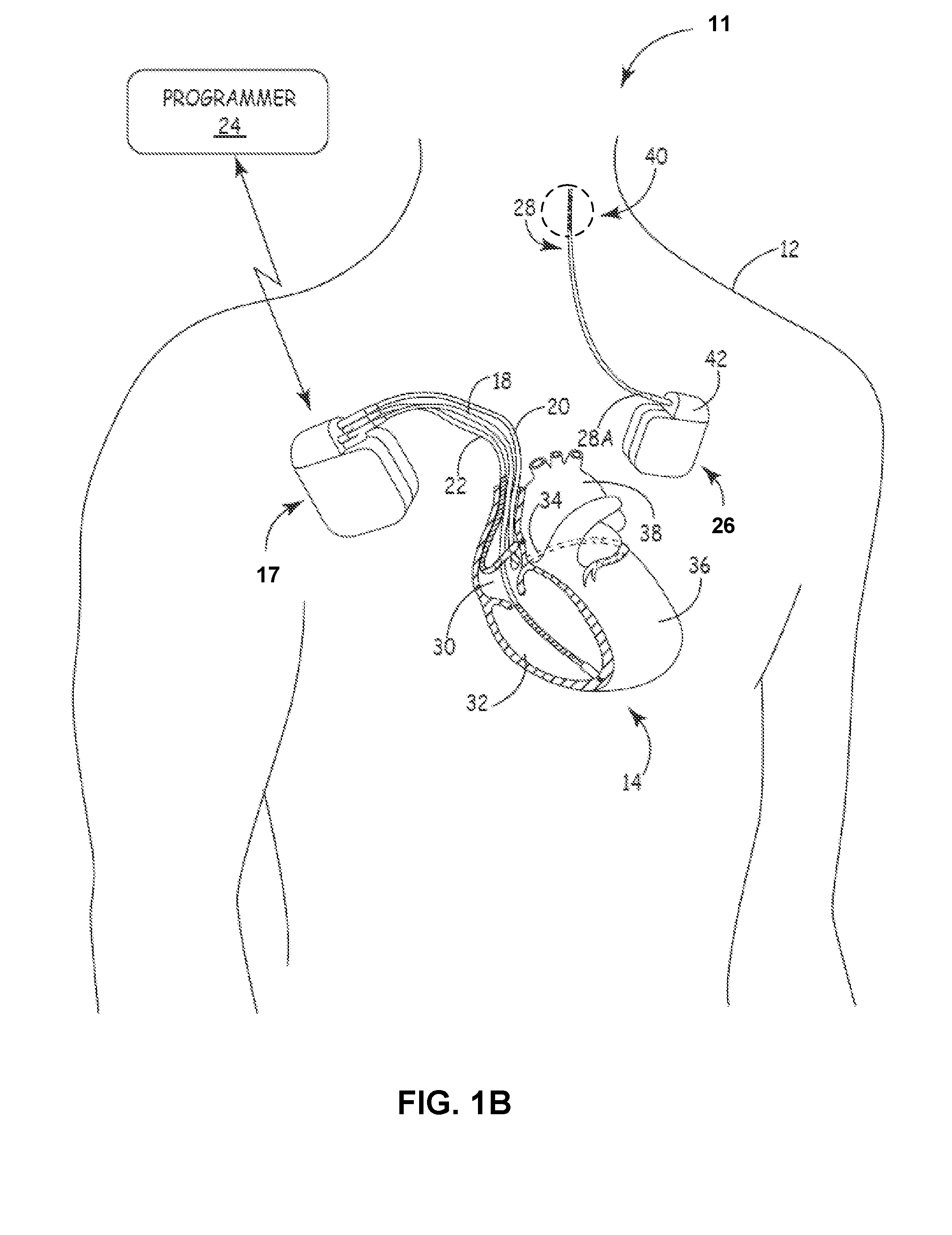
[0034]In general, this disclosure is directed toward techniques for placing medical leads proximate nerve tissue within a patient for electrical stimulation of the tissue without the use of potentially deleterious electrode configurations including e.g., cuff electrodes. Techniques disclosed herein are also generally directed to flexible placement techniques and structures that provide for one or more temporary lead placements and stimulation tests, prior to chronically placing the leads within the patient for nerve tissue stimulation. Furthermore, techniques according to this disclosure are adapted to enable minimally invasive introduction of the medical leads into the patient. Implantable electrical stimulation systems and methods in accordance with this disclosure may be used to deliver therapy to patients suffering from conditions that range from chronic pain, tremor, Parkinson's disease, and epilepsy, to urinary or fecal incontinence, sexual dysfunction, obesity, spasticity, an...


PUM


Abstract

This disclosure is directed to extra, intra, and transvascular medical lead placement techniques for arranging medical leads and electrical stimulation and/or sensing electrodes proximate nerve tissue within a patient.

Description

[0001]This application claims the benefit of U.S. Provisional Application Nos. 61 / 007,542, 61 / 007,543, 61 / 190,045, and 61 / 190,046, all of which were filed Apr. 30, 2008, and the entire contents of each of which is incorporated herein by this reference.TECHNICAL FIELD[0002]The disclosure relates to medical devices and, more particularly, medical devices that deliver electrical stimulation therapy.BACKGROUND[0003]A wide variety of implantable medical devices (“IMD”) that deliver therapy to or monitor a physiologic condition of a patient have been clinically implanted or proposed for clinical implantation in patients. Such devices may deliver therapy or monitor the heart, muscle, nerve, the brain, the stomach or other organs or tissues. In some cases, IMD's deliver electrical stimulation therapy and / or monitor physiological signals via one or more electrodes or sensor elements, at least some of which may be included as part of one or more elongated implantable medical leads. Implantabl...

Claims


Application Information

Patent Timeline
IPC IPC(8): A61M25/09A61N1/36A61N1/05
CPCA61N1/36053A61M25/09A61N1/05A61N1/0551A61N1/0558A61N1/36085A61N1/36114A61N1/36125A61N1/36128A61N1/057
Inventor BURNES, JOHN E.GARDESKI, KENNETH C.KLEPFER, RUTH N.MACAULAY, PATRICK E.MORRIS, MARY M.SCHEINER, AVRAM
Owner MEDTRONIC INC
Why Eureka
Try Eureka