Magnetic medium for magnetic encoder, magnetic encoder and method for manufacturing magnetic medium

a technology of magnetic encoder and magnetic encoder, which is applied in the direction of magnetic bodies, instruments, basic electric elements, etc., can solve the problems of disadvantageously being contaminated, and achieve the effects of reducing hysteresis errors, high reliability, and sufficient signal outpu

Inactive Publication Date: 2017-02-21
HITACHI METALS LTD
View PDF15 Cites 2 Cited by
  • Summary
  • Abstract
  • Description
  • Claims
  • Application Information

AI Technical Summary

Benefits of technology

[0012]In order to solve the above problems, the method II) has been considered which involves performing signal magnetization on the magnetic medium, and further applying a bias magnetic field in a direction perpendicular to the magnetic field caused by the signal magnetization. In this way, the bias magnetic field is applied in the direction perpendicular to the signal magnetization, whereby the in-plane component of the bias magnetic field in the magnetosensitive face can reduce the hysteresis error of the magnetic sensor in the region where the in-plane magnetic component of the signal magnetic field in the magnetosensitive face is almost eliminated (JP 55-59314 A). However, in order to apply the bias magnetic field to the signal magnetic field, a magnet or the like needs to be newly provided in the magnetic sensor and / or magnetic medium, which leads to an increase in size and cost of the magnetic sensor and / or magnetic medium. Further, it is difficult to effectively apply the bias magnetic field to the signal magnetic field region from the viewpoint of design.
[0014]The present disclosure has been made in view of the foregoing circumstances, and it is an object of the present disclosure to provide a magnetic medium, a magnetic encoder, and a method for manufacturing the magnetic medium with high reliability that can obtain sufficient signal output, while reducing the hysteresis error.
[0031]The present disclosure provides a magnetic medium, a magnetic encoder, and a method for manufacturing a magnetic medium with high reliability that can obtain the sufficient signal output, while reducing the hysteresis error.

Problems solved by technology

The optical encoder is advantageously less likely to be affected by a peripheral magnetic field, but disadvantageously more likely to be contaminated by dust, oil, or the like.

Method used


Image

  • Magnetic medium for magnetic encoder, magnetic encoder and method for manufacturing magnetic medium
  • Magnetic medium for magnetic encoder, magnetic encoder and method for manufacturing magnetic medium
  • Magnetic medium for magnetic encoder, magnetic encoder and method for manufacturing magnetic medium

Examples


first embodiment

(First Embodiment)

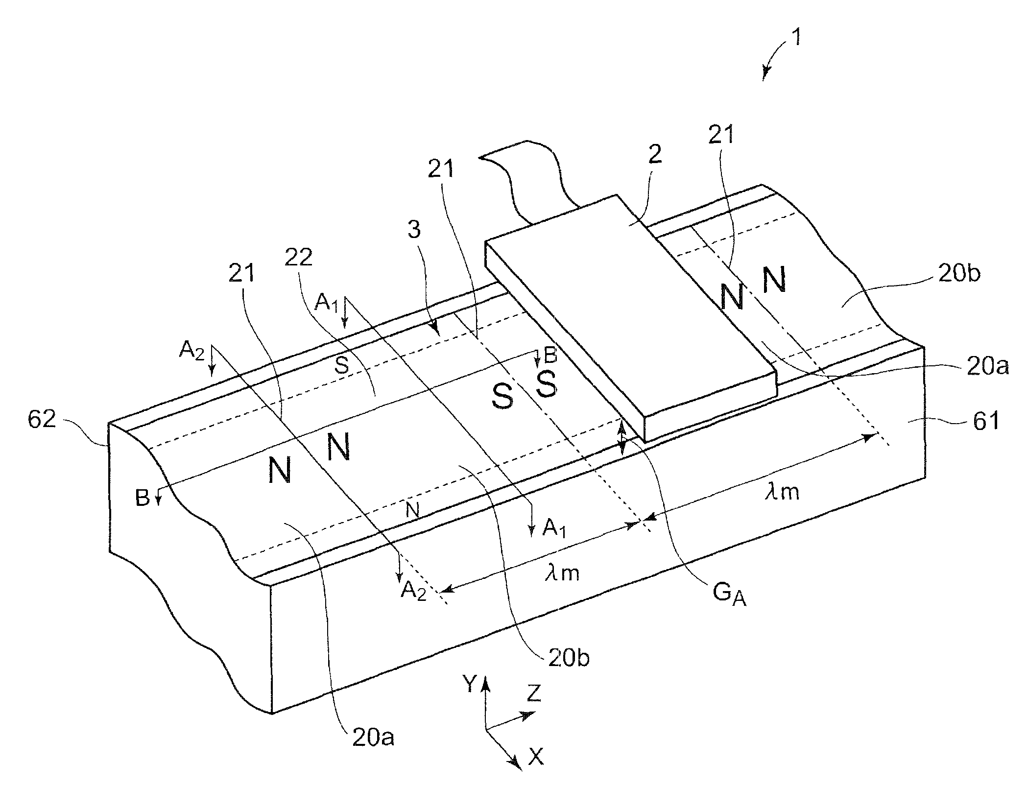
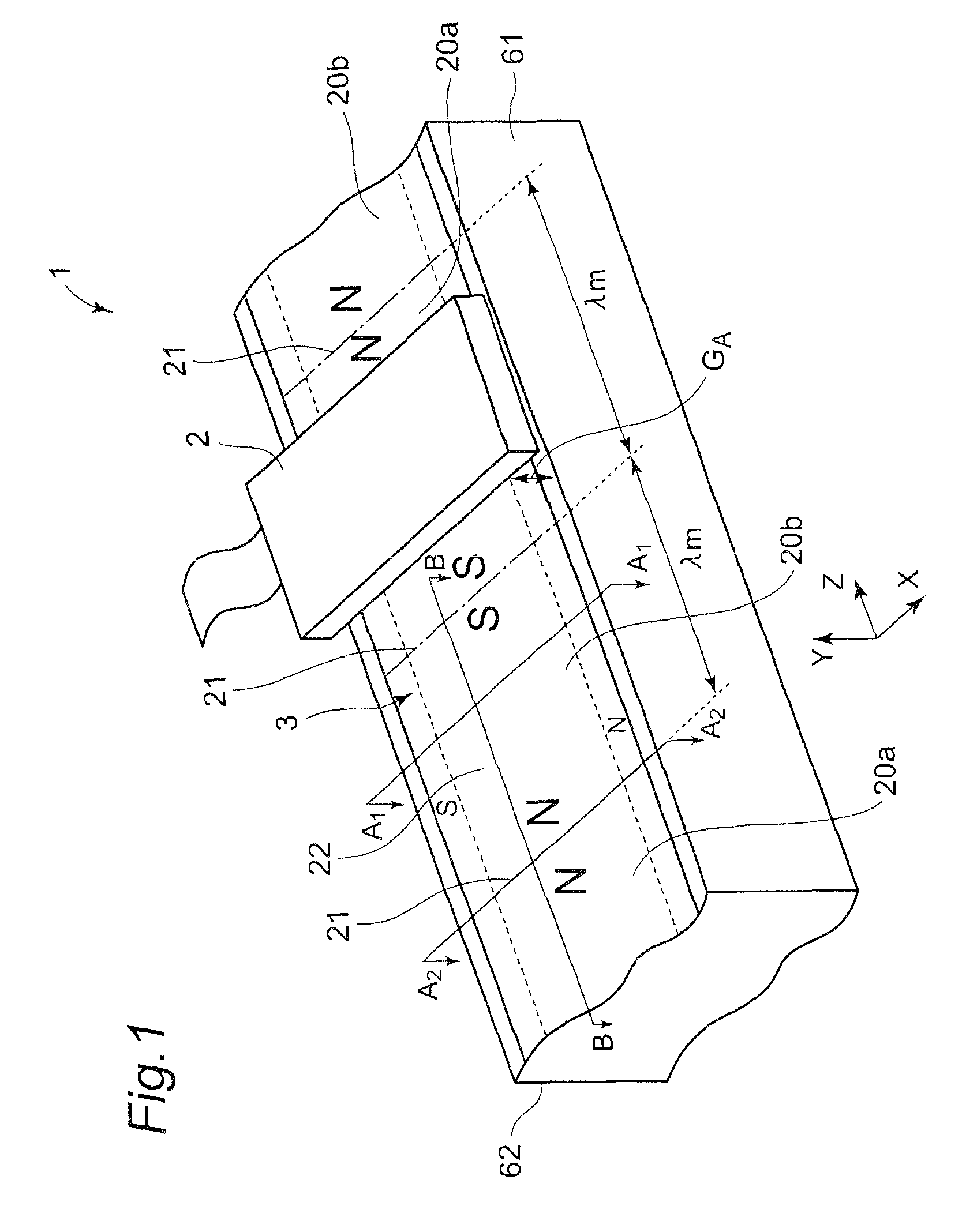
[0047]For better understanding of the present disclosure, first, the structure and function of a magnetic encoder including a magnetic sensor with a magnetoresistive effect element and a magnetic medium will be described below with reference to FIG. 1. The magnetic medium can be linearly provided to produce a linear type magnetic encoder. Alternatively, a ring-like magnetic medium can be provided over an outer peripheral surface of a drum in a ring-like shape to produce a drum magnetic encoder. Therefore, it is to be understood to those skilled in the art that the drum magnetic encoder can be implemented based on a specific example of the linear magnetic encoder below.

[0048]FIG. 1 is a schematic diagram of a linear magnetic encoder (hereinafter simply referred to as a “magnetic encoder or encoder”) 1 according to one embodiment of the present invention. As shown in FIG. 1, the linear magnetic encoder 1 of one embodiment of the present invention includes a magnetic ...

example 1

[0096]In a magnetic encoder 1 subjected to the bias magnetization and the signal magnetization according to the first embodiment of the present invention, the magnetic medium 3 was moved in each of the left and right directions with respect to the magnetic sensor 2 by 3 mm, and in the respective movements, outputs from the magnetic encoder 1 were measured. The result is shown in FIG. 3B.

example 2

[0097]In the magnetic encoder subjected to the bias magnetization and the signal magnetization in the first embodiment of the present invention, the air gap GA as a distance between the magnetic sensor and the magnetic medium was changed in a range from 50 μm to 400 μm to thereby determine the output amplitude (see FIG. 9) and accumulated error (see FIG. 10). The output amplitude is shown in FIG. 9 and the accumulated error is shown in FIG. 10.


PUM

PropertyMeasurementUnit
electric angleaaaaaaaaaa
magnetic fieldaaaaaaaaaa
magnetizationaaaaaaaaaa

Abstract

The present disclosure provides a magnetic medium, a magnetic encoder, and a method for manufacturing a magnetic medium with high reliability that can obtain the sufficient signal output, while reducing the hysteresis error. The magnetic medium is relatively movable with respect to a magnetic sensor for detecting a magnetic field in a magnetosensitive face.

Description

CROSS REFERENCE TO RELATED APPLICATIONS[0001]This patent application claims the benefit of priority from Japanese Patent Application No. 2013-223166 filed on Oct. 28, 2013, the entire contents of which are incorporated herein by reference thereto.BACKGROUND OF THE INVENTION[0002]Field of the Invention[0003]The present disclosure relates to a magnetic encoder for detecting a movement direction or movement amount of a moving member, or a rotation angle of a rotary body using a change in magnetism, a magnetic medium used for the magnetic encoder, and a method for manufacturing the same.[0004]Description of the Related Art[0005]Encoders are used in devices / apparatuses that require a precise control of the movement direction, movement amount, rotation angle, or the like.[0006]The encoders are mainly classified into an optical encoder and an electromagnetic induction encoder based on the principle of operation.[0007]The optical encoder is advantageously less likely to be affected by a per...

Claims


Application Information

Patent Timeline
Patent Type & Authority Patents(United States)
IPC IPC(8): H01F13/00G01D5/16G01D5/20H01F41/00
CPCG01D5/16G01D5/2033H01F13/00H01F41/00Y10T29/4902
Inventor ABE, YASUNORIKAWAKAMI, MAKOTO
Owner HITACHI METALS LTD
Why Eureka
Try Eureka