Optical deflector including mirror with extended reinforcement rib coupled to protruded portions of torsion bar

a technology of optical deflector and reinforcement rib, which is applied in the field of optical deflector including, can solve the problems of mirror completely breaking down, mirror rigidity is very small, and the optical scanning characteristics of reflected light of the mirror would not meet the optical scanning characteristics of high-definition projector optical scanners, etc., and achieve the effect of improving the optical scanning characteristics of reflected light from the mirror

Active Publication Date: 2017-02-21
STANLEY ELECTRIC CO LTD
View PDF11 Cites 3 Cited by
  • Summary
  • Abstract
  • Description
  • Claims
  • Application Information

AI Technical Summary

Benefits of technology

[0017]Thus, according to the presently disclosed subject matter, when the rocking angle of the mirror is large, although a relatively large stress as a repulsive force spread from the torsion bar is concentrated at a portion of the torsion bar in the vicinity of the protruded portions thereof, no substantial stress occurs in a portion of the mirror surrounded by the extension portions of the reinforcement rib. Therefore, the portion of the mirror surrounded by the extension portions reinforcement rib would not be distorted, i.e., the entire mirror would not be distorted, so that the optical scanning characteristics of reflected light from the mirror would improve. Additionally, the ring-shaped reinforcement rib would not be peeled off.

Problems solved by technology

In the first prior art optical deflector, however, since the mirror is very thin, the rigidity of the mirror is very small.
Thus, the optical scanning characteristics of reflected light of the mirror would not satisfy the required optical scanning characteristics in optical scanners for high definition projectors.
At worst, the mirror entirely would break down.
Therefore, the portions of the mirror between the torsion bars and the ring-shaped reinforcement rib would be distorted, so that the optical scanning characteristics of reflected light from the mirror would still deteriorate.
Therefore, the portions of the mirror surrounded by the extension portions of the ring-shaped reinforcement rib would be distorted, so that the optical scanning characteristics of reflected light from the mirror would still deteriorate.

Method used


Image

  • Optical deflector including mirror with extended reinforcement rib coupled to protruded portions of torsion bar
  • Optical deflector including mirror with extended reinforcement rib coupled to protruded portions of torsion bar
  • Optical deflector including mirror with extended reinforcement rib coupled to protruded portions of torsion bar

Examples


Embodiment Construction

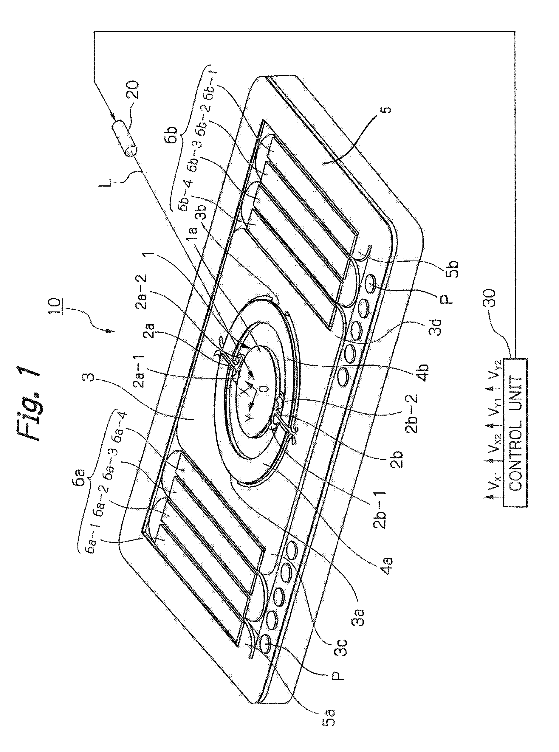
[0032]In FIG. 1, which illustrates an embodiment of the two-dimensional optical deflector according to the presently disclosed subject matter, reference numeral 10 designates a two-dimensional optical deflector, 20 designates a laser light source, and 30 designates a control unit for controlling the optical deflector 10 and the laser light source 20.

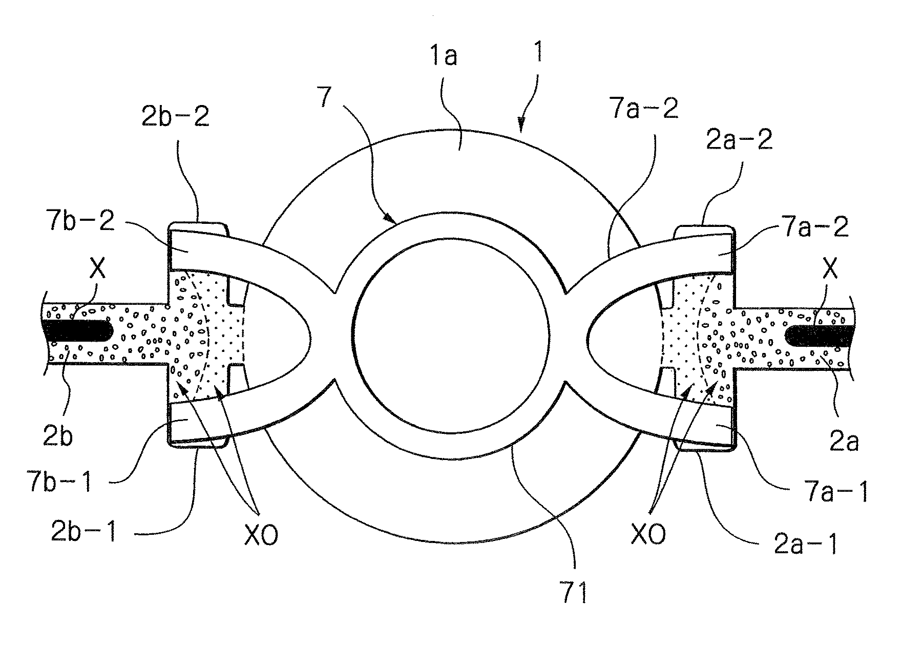
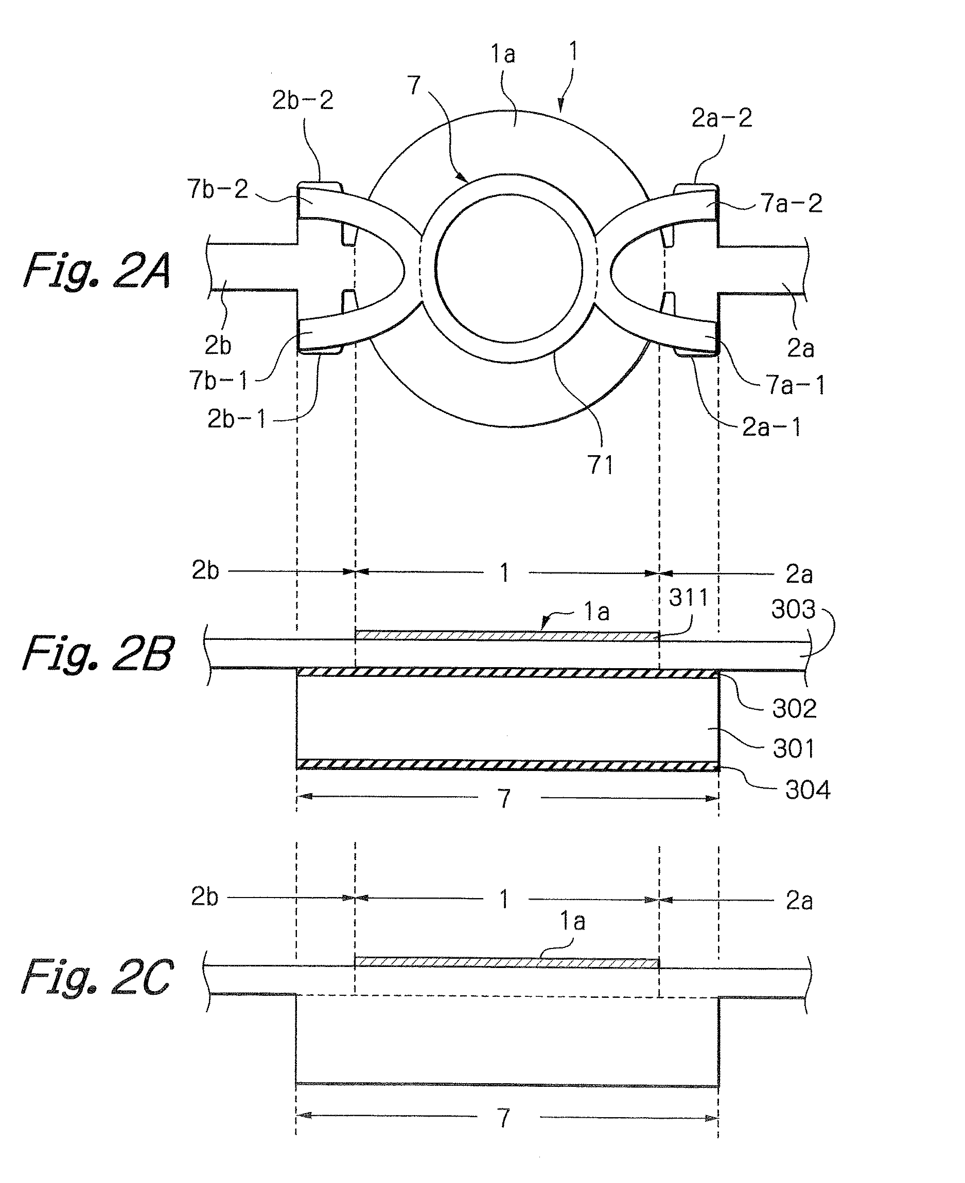
[0033]The optical deflector 10 is constructed by a circular mirror 1 with a reflective layer 1a on its front surface for reflecting incident light L from the laser light source 20, a pair of torsion bars 2a and 2b coupled to the mirror 1 along an X-axis, an inner frame (movable support frame) 3 surrounding the mirror 1 and the torsion bars 2a and 2b for supporting the mirror 1, a semi-ring shaped inner piezoelectric actuator 4a coupled between the torsion bars 2a and 2b and supported by an inner coupling portion 3a of the inner frame 3, and a semi-ring shaped inner piezoelectric actuator 4b coupled between the torsion bars 2a and 2b and ...


PUM


Abstract

An optical deflector includes a mirror with a reflective layer on its front-side surface, a first support frame adapted to support the mirror, at least one torsion bar coupled between the first support frame and the mirror; and a reinforcement rib provided on a rear-side surface of the mirror. The torsion bar has a pair of protruded portions arranged symmetrically with respect to the torsion bar in the vicinity of a coupling portion between the torsion bar and the mirror. The reinforcement rib has a central portion and a pair of extension portions extended symmetrically from the central portion and coupled to the protruded portions, respectively, of the torsion bar.

Description

[0001]This application claims the priority benefit under 35 U. S. C. §119 to Japanese Patent Application No. JP2015-051862 filed on Mar. 16, 2015, which disclosure is hereby incorporated in its entirety by reference.BACKGROUND[0002]Field[0003]The presently disclosed subject matter relates to an optical deflector used in an optical scanner for a projector, a laser headlamp, a bar code reader, a laser printer, a laser head amplifier, a head-up display unit and the like.[0004]Description of the Related Art[0005]Recently, optical deflectors used in optical scanners have been micro electro mechanical system (MEMS) devices manufactured by semiconductor manufacturing technology and micro machine technology.[0006]A first prior art optical deflector is constructed by a mirror supported by torsion bars to a support frame. Also, provided between the support frame and the torsion bars are actuators serving as cantilevers. Thus, the mirror can be rocked around an axis by the actuators.[0007]In t...

Claims


Application Information

Patent Timeline
Patent Type & Authority Patents(United States)
IPC IPC(8): G02B26/08G02B26/10
CPCG02B26/101G02B26/0833G02B26/0858
Inventor FUJIMOTO, KENJIRO
Owner STANLEY ELECTRIC CO LTD
Why Eureka
Try Eureka