
Systems and methods for regulating inductive energy transfer to an implantable system

a technology of inductive energy transfer and implantable devices, which is applied in the direction of wound drains, transportation and packaging, and treatment, etc., can solve the problems of increasing wear and tear of mechanical components, deteriorating circuitry, and damage to the electromechanical components and circuitry disposed within the implantable device, so as to reduce the generation of ohmic heating

Active Publication Date: 2017-02-21
SEQUANA MEDICAL NV
View PDF18 Cites 13 Cited by
  • Summary
  • Abstract
  • Description
  • Claims
  • Application Information

AI Technical Summary

Benefits of technology

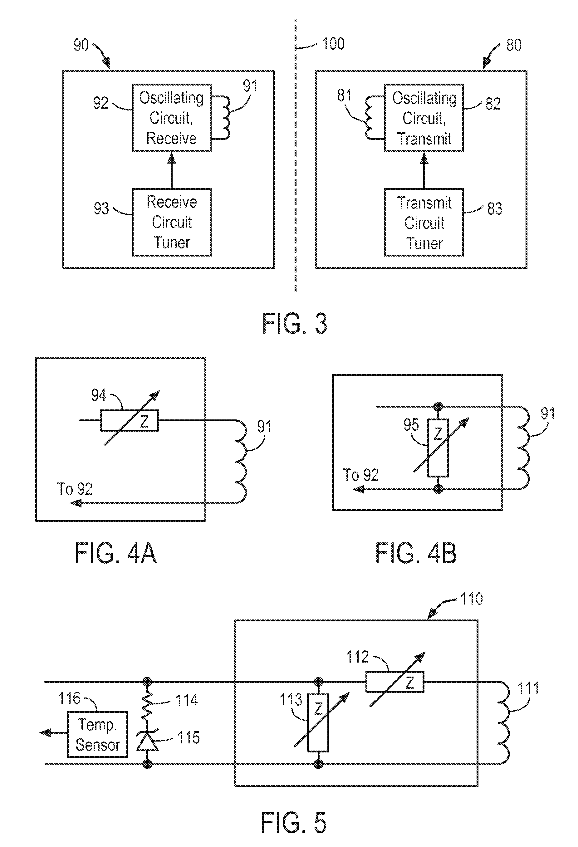
[0011]In accordance with one aspect of the present invention, an inductive charging system for an implantable device, and methods of use, are provided that limit temperature excursions within the receiving circuit of the implantable device by directly regulating energy absorption of the receiving circuit in real-time, without a time lag associated with transmission and analysis of data from the implantable device to an external charging system.
[0012]In accordance with another aspect of the present invention, circuits and methods for regulating energy absorption by the receiving circuit of an implantable device are provided that reduce generation of ohmic heating within the receiving circuit.
[0014]In some embodiments, the implantable device may include a microprocessor or dedicated logic for monitoring the sensor and adjusting parameters of the receiving circuit to reduce energy absorption by the receiving circuit.

Problems solved by technology

As described in the foregoing application, circuitry within the implantable device may heat up in response to the current flowing through the receiving coil or the voltage built up across the receiving coil, causing damage to the electromechanical components and circuitry disposed within the implantable device.
Specifically, such heating may cause deterioration of the circuitry in the implantable device, or increased wear in mechanical components of the implantable device due to reduced clearances between components.
Heating also may cause degradation of a humidity barrier over implant circuitry, thereby allowing moisture into the circuitry, possibly causing improper performance or implant damage.
In addition, if the temperature of the circuitry increases too much, excessive heat may be transferred to the tissue surrounding the implantable device, causing discomfort or injury to that tissue.

Method used


Image

  • Systems and methods for regulating inductive energy transfer to an implantable system
  • Systems and methods for regulating inductive energy transfer to an implantable system
  • Systems and methods for regulating inductive energy transfer to an implantable system

Examples


Embodiment Construction

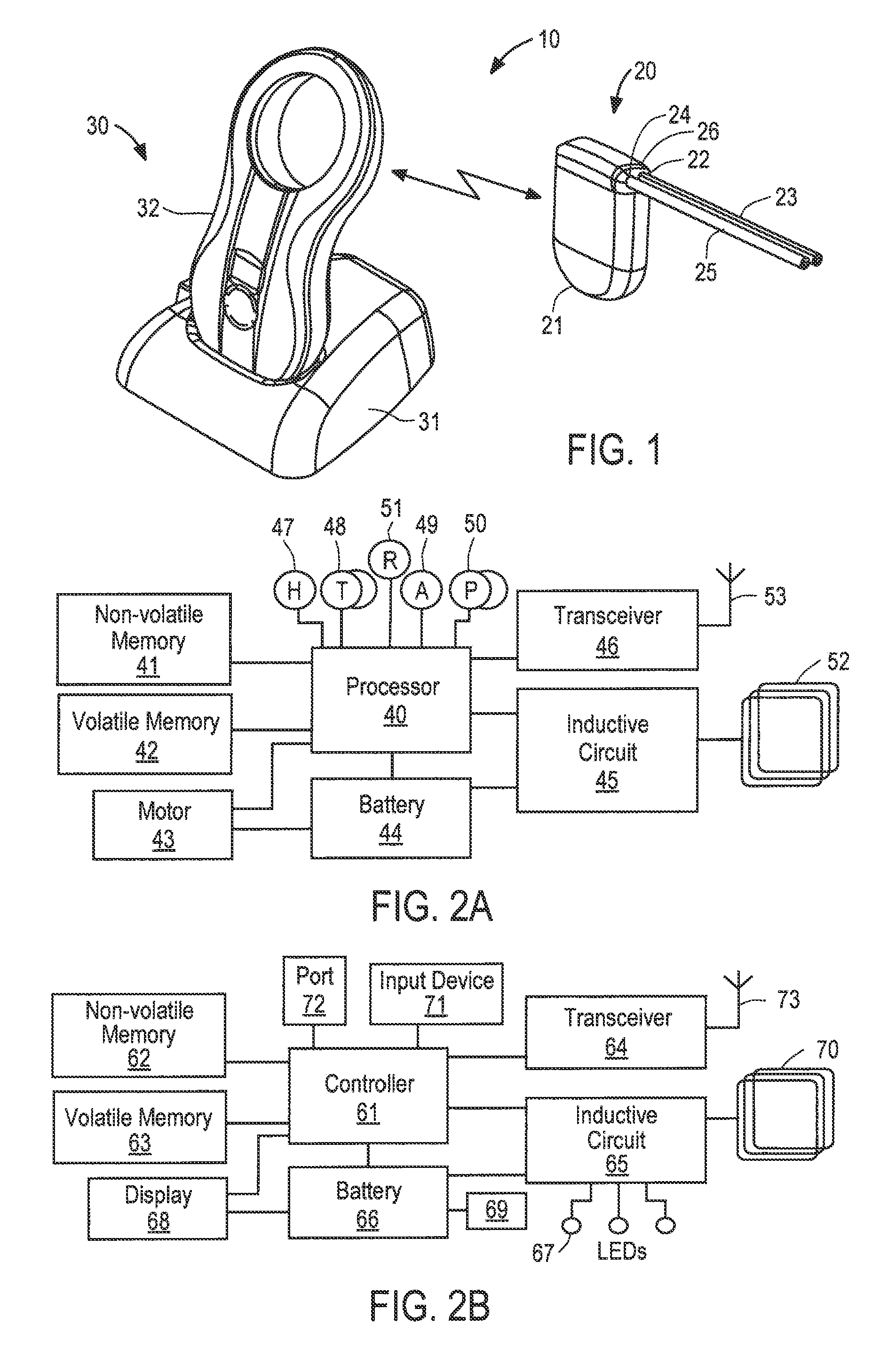
[0022]Referring to FIGS. 1, 2A and 2B, an exemplary embodiment of a system suitable for use with the inductive charging system of the present invention is described. System 10 is similar to that described in U.S. Patent Application Publication No. US 2012 / 0209165 A1 to Degen et al., assigned to the assignee of the present application, the entirety of which is incorporated herein by reference. System 10 illustratively comprises implantable device 20, and external charging system 30. As described in the incorporated application, system 10 also may include a monitoring and control system (not shown) that communicates with external charging system. As will be understood, implantable device 20 is configured to be implanted subcutaneously within a human body, while external charging system 30 is configured to be periodically placed over the skin in the vicinity of the implantable device to charge and communication with the implantable device.

[0023]Implantable device 20 illustratively comp...


PUM


Abstract

Systems and methods are provided for regulating the transfer of energy inductively between an implantable device and an external charging system, wherein the energy transfer rate is regulated by varying an operating frequency of an inductive energy transfer circuit of the implantable device responsive a temperature measured within the implantable device.

Description

FIELD OF THE INVENTION[0001]The present invention is directed to the field of inductive charging of implantable devices, and more particularly, to regulating inductive charging of implantable devices to prevent excessive heat build-up or overcharging of a battery within the implantable device.BACKGROUND OF THE INVENTION[0002]There are many power-consuming devices designed to be implanted in the body of a human. Such devices frequently include a power source, such as a battery, that must be periodically recharged for the device to remain functional. Alternatively or additionally, an implantable device may receive operational power from an external charging system, for example, via an inductive charging circuit. For example, U.S. Patent Application Publication No. US 2012 / 0209165 A1 to Degen et al., assigned to the assignee of the present application, describes an example in which an implantable device, including an electro-mechanical pump is powered by a rechargeable battery, which i...

Claims


Application Information

Patent Timeline
Patent Type & Authority Patents(United States)
IPC IPC(8): H02J7/00H02J7/02A61M5/142A61N1/378A61M27/00
CPCH02J7/025A61M5/14276A61N1/3787H02J7/007A61M2027/004A61M2205/3538A61M2205/3569A61M2205/8243H02J50/12
Inventor DEGEN, THOMAS WERNERTSCHUMPER, STEFAN
Owner SEQUANA MEDICAL NV
Learn More