Supporting rack

a technology for supporting racks and devices, applied in the direction of dismountable cabinets, trays, instruments, etc., can solve the problems of monotonous conventional supporting racks, difficulty in installation and adjustment, and the drawback of suspension support devices, so as to increase the applicability of supporting racks

Inactive Publication Date: 2017-02-28
CHEN-SOURCE INC
View PDF91 Cites 33 Cited by
  • Summary
  • Abstract
  • Description
  • Claims
  • Application Information

AI Technical Summary

Benefits of technology

[0009]The present invention has been accomplished under the circumstances in view. It is the main object of the present invention to provide a supporting rack, which comprises two foot members arranged in parallel, two support members vertically adjustably mounted on the respective foot members, and a tabletop detachably fastened to the support members in horizontal. Each foot member comprises a hollow foot member body, a foot member cover and two binding members fastened to the hollow foot member body to secure the foot member cover to the hollow foot member body. The hollow foot member body comprises a plurality of mounting slots transversely located in the top wall thereof, an accommodation chamber defined therein and an opening defined in an inner lateral side thereof in communication with the accommodation chamber. The foot member cover is adapted for covering the opening of the hollow foot member body, comprising a cover base inserted through the opening into the accommodation chamber and a plurality of locating blocks symmetrically extended from two opposite lateral sides of the cover base at different elevations and engaged into the inside of the hollow foot member body. The two binding members are detachably fastened to the hollow foot member body at two opposite sides to secure the foot member cover to the hollow foot member body. The two support members vertically adj

Problems solved by technology

When using a screen rack to support the display screen on the desk, the screen rack will occupy much desktop space.
However, a suspension support device has the drawbacks of installation difficulty and adjustment inconvenience.
However, t

Method used


Image

  • Supporting rack
  • Supporting rack
  • Supporting rack

Examples


Embodiment Construction

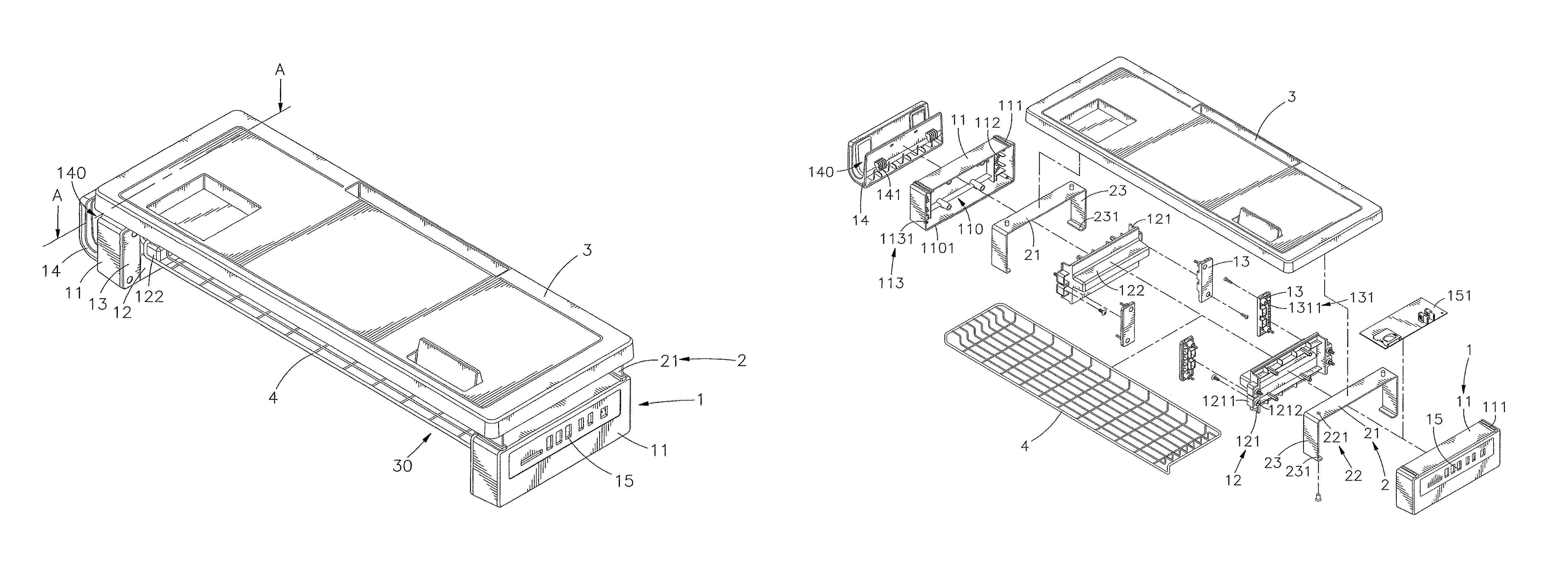
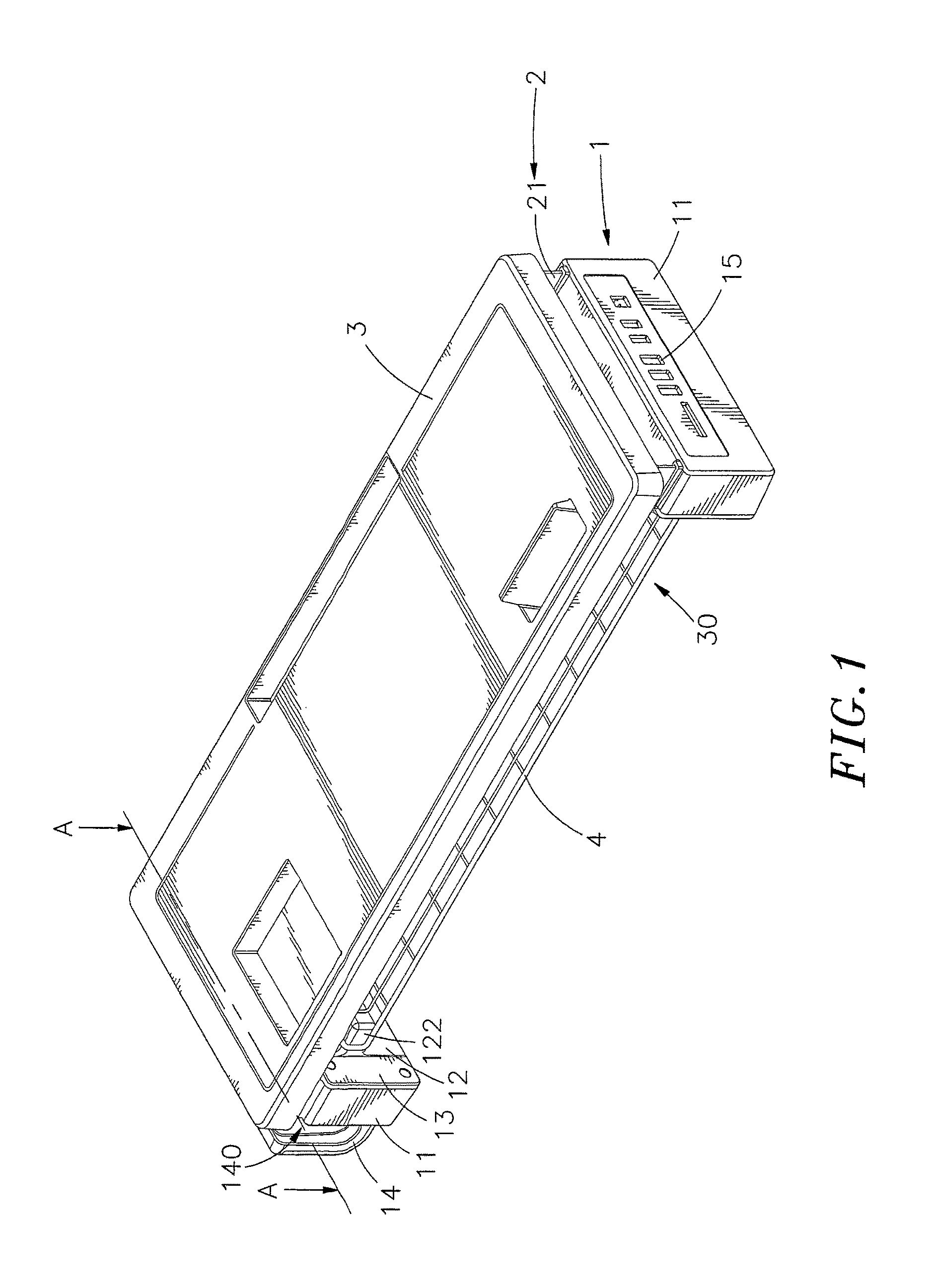
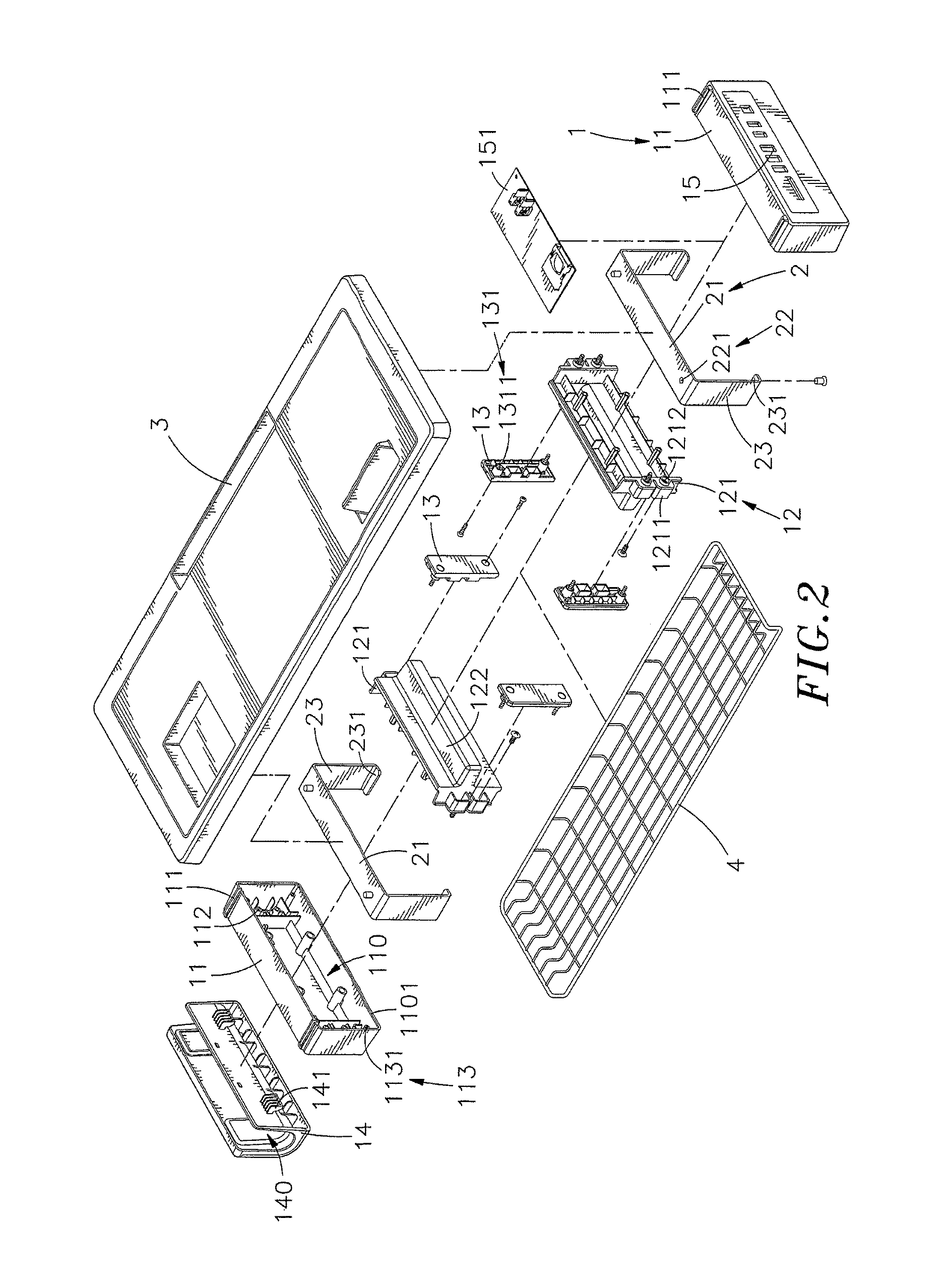
[0021]Referring to FIGS. 1-4, a supporting rack in accordance with the present invention is shown. The supporting rack comprises two foot members 1, two support members 2 and a tabletop 3.

[0022]The foot member 1 comprises a hollow foot member body 11, a foot member cover 12 and two binding members 13. The hollow foot member body 11 comprises a plurality of mounting slots 111 located in a top wall thereof and transversely cut through one side of the top wall, an accommodation chamber 110 defined therein, and an opening 1101 defined in an inner lateral side thereof in communication with the accommodation chamber 110. The foot member cover 12 is mounted in the opening 1101 of the hollow foot member body 11, comprising a cover base 121 engaged into the accommodation chamber 110 and a plurality of locating blocks 1211 symmetrically extended from two opposite lateral sides of the cover base 121 at different elevations and engaged into the inside of the hollow foot member body 11. The two ...


PUM


Abstract

A supporting rack includes two foot members each including a hollow foot member body, a foot member cover covering the hollow foot member body and two binding members bilaterally and detachably fastened to the hollow foot member body to secure the foot member cover in place, two support members vertically adjustably mounted on the respective foot members and locked by the respective binding members, a tabletop detachably supported on the support members and adjustable with the support members relative to the foot members to the desired elevation and defining a receiving space between the two foot members beneath the bottom wall thereof for accommodating computer keyboard, mouse or other peripheral devices.

Description

BACKGROUND OF THE INVENTION[0001]1. Field of the Invention[0002]The present invention relates to device supporting racks and more particularly to such a supporting rack, which comprises two foot members, two support members vertically adjustably mounted on the respective foot members, and a tabletop detachably supported on the support members and adjustable with the support members relative to the foot members to the desired elevation.[0003]2. Description of the Related Art[0004]With fast development of electronic and multimedia technologies, advanced and sophisticated computer, notebook computer and many other mobile electronic devices have been continuously created and widely used around every corner in our society. Due to the popularization of computers, most people are dependent on computers. Nowadays, people often use a keyboard, mouse and other computer peripheral equipment to provide electrical signals to a computer, enabling the computer to output the content of the electric...

Claims


Application Information

Patent Timeline
IPC IPC(8): A47B47/00A47B23/04H05K7/18H05K7/02A47B21/04A47B21/03A47B81/00
CPCA47B21/0314A47B21/04A47B23/04A47B81/00H05K7/02H05K7/18A47B2200/0066A47B47/00A47B2200/0013G06F1/1632A47B23/001A47G23/06A47G23/0608A47G23/0641
Inventor WU, KUAN-YEN
Owner CHEN-SOURCE INC
Why Eureka
Try Eureka