Sliding parts

a technology of sliding parts and parts, applied in the direction of bearing components, shaft and bearings, bearing seals, etc., to achieve the effect of facilitating uniform streamline-shape flow and easy formation

Active Publication Date: 2017-02-28
EAGLE INDS
View PDF19 Cites 0 Cited by
  • Summary
  • Abstract
  • Description
  • Claims
  • Application Information

AI Technical Summary

Benefits of technology

[0033](1) Since the groove width of the outlet side section of the fluid circulation groove is gradually expanded toward the outlet end, no stagnation is formed in the vicinity of the outlet end of the outlet side section of the fluid circulation groove, and the sealed fluid flows as a uniform streamline-shape flow from the vicinity of the outlet end toward the downstream side while receiving the centrifugal force. Thus, the sealed fluid is not attached to the side wall on the outer peripheral side of the sealing face S but moved to the downstream side away from the side wall, and the flow of the sealed fluid discharged from the fluid circulation groove on the upstream side goes around the position away from the inlet end of the fluid circulation groove on the downstream side in the radial direction, and does not flow into the fluid circulation groove on the downstream side again.
[0034]Therefore, unlike the prior art, the phenomenon that the sealed fluid discharged from the fluid circulation groove on the upstream side flows into the fluid circulation groove on the downstream side again and by repeating this, the sealed fluid is gradually concentrated to finally become a sticky paste form and attached and accumulated onto the interior of the fluid circulation groove is not generated. As a result, the fluid circulation groove is always held in a clean state, so that the lubricity of the sealing face can be maintained in a preferable state.
[0035](2) Since the groove width of the inlet side section of the fluid circulation groove is gradually expanded toward the inlet end, no stagnation of the flow is formed in the vicinity of the inlet end of the inlet side section of the fluid circulation groove, so that the fluid efficiently flows into the inlet side section as a uniform flow.
[0036](3) Since both the side walls of the groove in the outlet side section of the fluid circulation groove are expanded in a streamline shape toward the outlet end and both the side walls of the groove in the inlet side section are expanded in a streamline shape toward the inlet end in a plan view of the sealing face, stagnation formation in the vicinity of the outlet end of the outlet side section of the fluid circulation groove and in the vicinity of the inlet end of the inlet side section is furthermore prevented, and a uniform streamline-shape flow can be furthermore facilitated.
[0037](4) Since the streamline shape of both the side walls of the groove in each of the outlet side section and the inlet side section is created by the arcs in contact with the extension lines of both the side walls of the groove in each of the outlet side section and the inlet side section, the streamline shape of both the side walls of the groove in each of the outlet side section and the inlet side section can be easily formed.
[0038](5) Since the bottom wall of the groove in the outlet side section or the inlet side section is formed to be deep in a streamline shape toward the end of the respective groove, a uniform streamline-shape flow of the sealed fluid from the vicinity of the outlet end toward the downstream side and an inflow of a new sealed fluid from the vicinity of the inlet end are furthermore facilitated.

Problems solved by technology

However, a mechanical seal to offer a measure for preventing generation of sediment on a sealing face in addition to reduction in leakage and wear is not proposed in a current situation.

Method used


Image

  • Sliding parts
  • Sliding parts
  • Sliding parts

Examples


first embodiment

[0048

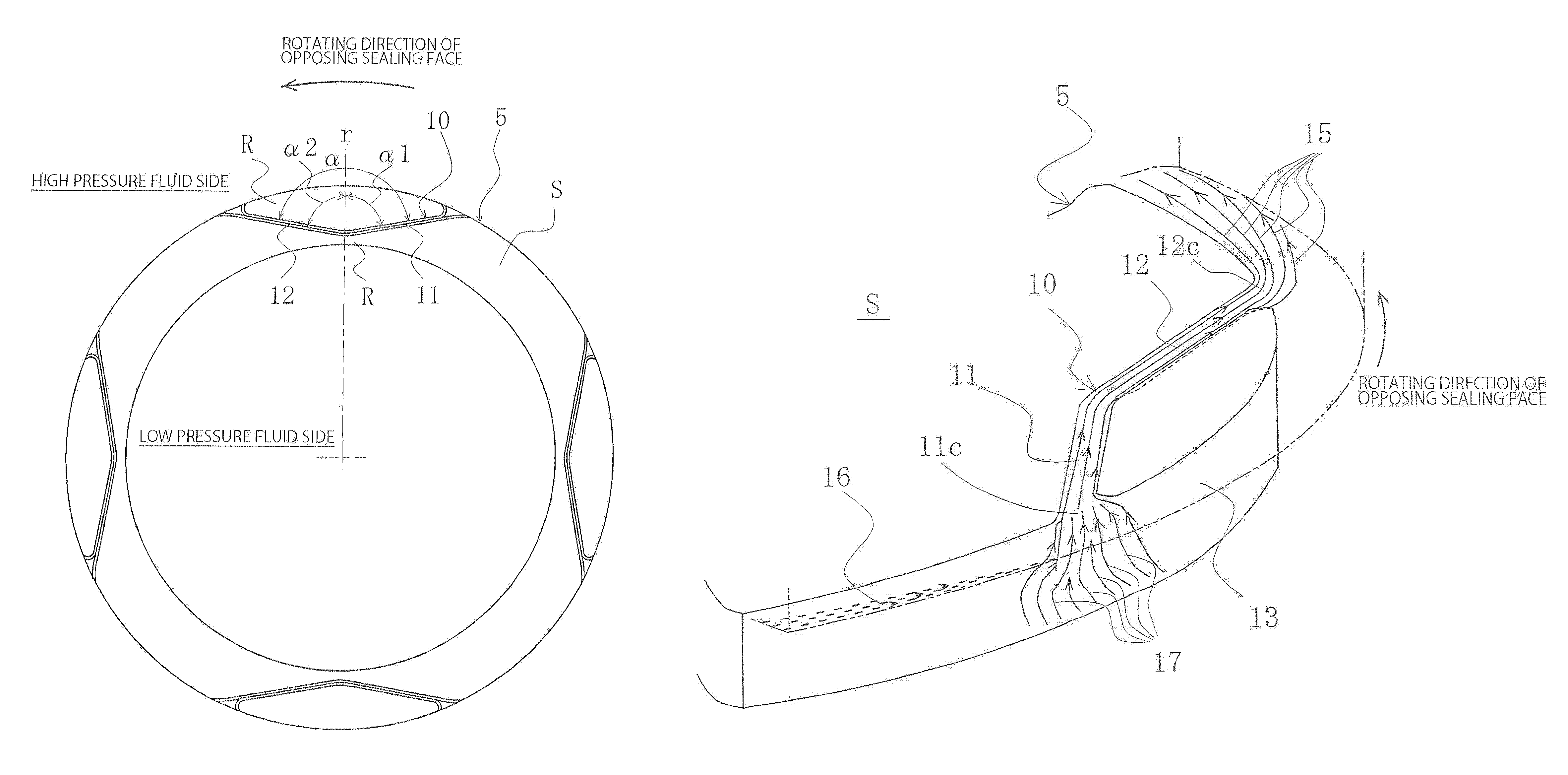
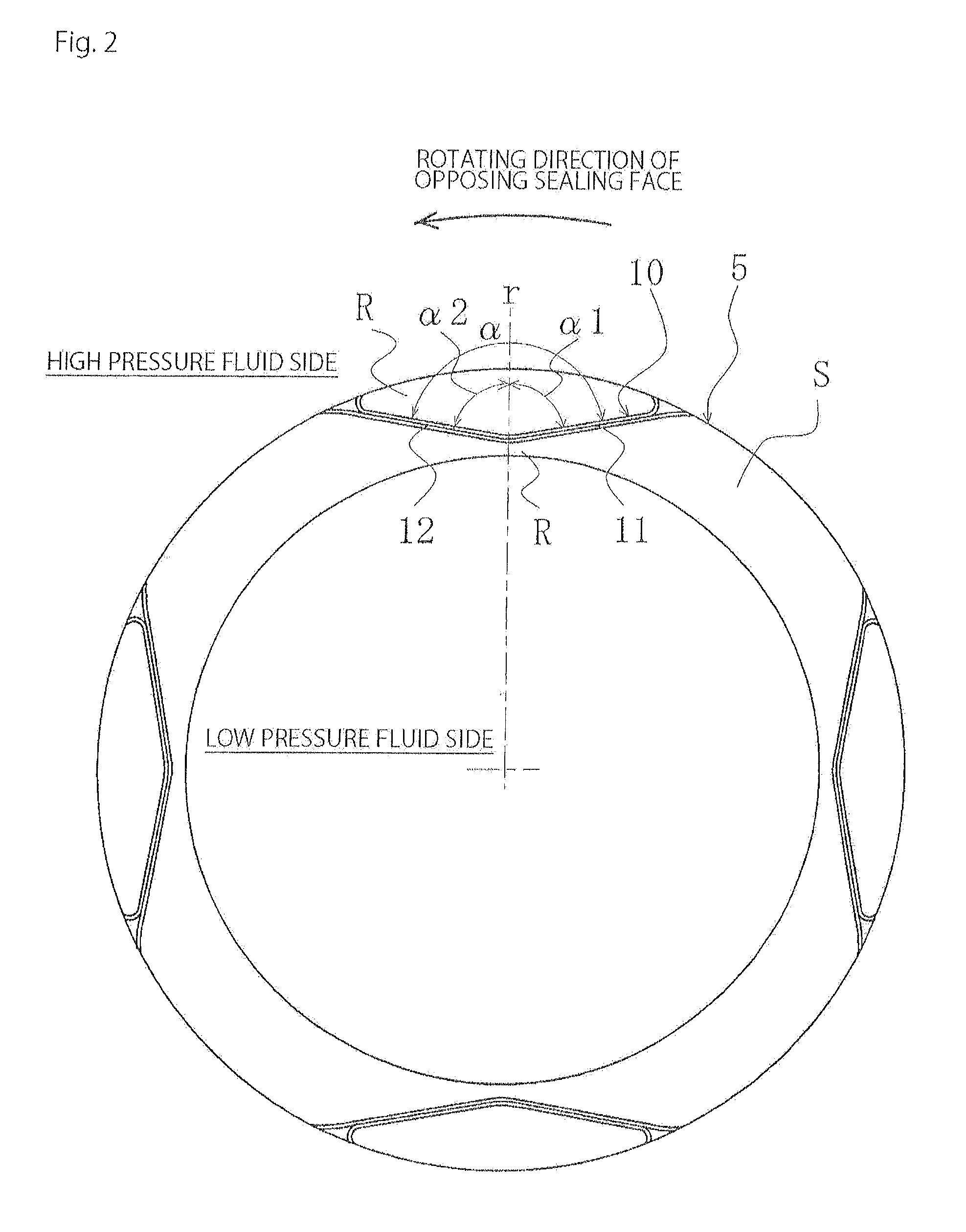
[0049]With reference to FIGS. 1 to 4, sliding parts according to a first embodiment of the present invention will be described.

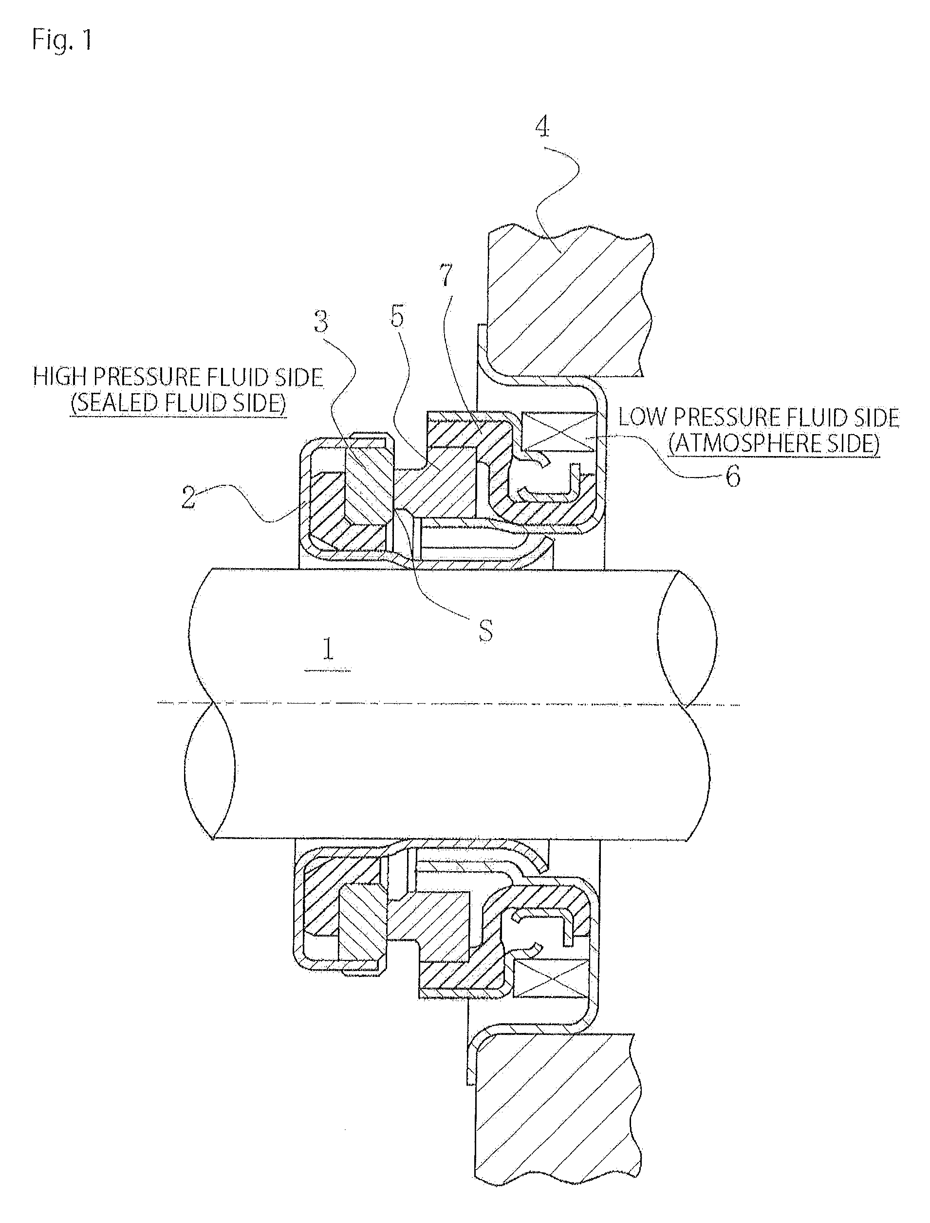
[0050]It should be noted that in the following embodiment, a mechanical seal serving as one example of the sliding parts will be described as an example. In the description, an outer peripheral side of the sliding parts that form the mechanical seal serves as a high pressure fluid side (sealed fluid side), and an inner peripheral side serves as a low pressure fluid side (atmosphere side). However, the present invention is not limited to this but can also be applied to a case where the high pressure fluid side and the low pressure fluid side are set the other way around.

[0051]FIG. 1 is a vertically sectional view showing one example of the mechanical seal that is an inside mechanical seal for sealing a sealed fluid on the high pressure fluid side to be leaked out from an outer periphery of a sealing face toward an inner periphery. In the mechanical seal,...


PUM


Abstract

A fluid is actively taken into sealing faces and discharged from the sealing faces to prevent concentration of sediment causative substances on the sealing faces and prevent generation of sediment while preventing leakage of the fluid taken into the sealing faces to a low pressure fluid side. A fluid circulation groove includes an inlet side section where the fluid comes in from a high pressure fluid side and an outlet side section where the fluid goes out to the high pressure fluid side in one of sealing faces of a pair of sliding parts that slide on each other. The fluid circulation groove is isolated from the low pressure fluid side by a land section. Groove width of the outlet side section of the fluid circulation groove is gradually expended toward an outlet end.

Description

TECHNICAL FIELD[0001]The present invention relates to sliding parts suitable for a mechanical seal, a bearing, and other sliding portions for example. In particular, the present invention relates to sliding parts such as a sealing ring or a bearing in which a fluid lies on sealing faces to reduce friction and there is a need for preventing fluid leakage from the sealing faces.BACKGROUND ART[0002]In a mechanical seal serving as one example of the sliding parts, performances thereof are evaluated by a leakage amount, a wear amount, and torque. In the prior art, the performances are enhanced by optimizing sliding material and sealing face roughness of the mechanical seal, so as to realize low leakage, long life, and low torque. However, due to raising awareness of environmental problems in recent years, further improvement in the performances of the mechanical seal is required, and there is a need for technical development going beyond the boundary of the prior art.[0003]Under such cir...

Claims


Application Information

Patent Timeline
Patent Type & Authority Patents(United States)
IPC IPC(8): F16J15/34F16C33/74
CPCF16C33/74F16J15/3412
Inventor ITADANI, MASATOSHISUNAGAWA, KAZUMASATOKUNAGA, YUUICHIROYAMAKAWA, RYOMA
Owner EAGLE INDS
Why Eureka
Try Eureka