Mechanical seal

a mechanical seal and plate technology, applied in the direction of engine seals, mechanical apparatus, engine components, etc., can solve the problems of deformation or tearing of bent parts, and achieve the effects of reducing the change in the amount of stretching and contracting reducing the plate thickness and reducing the spring constant of the metal bellows

Active Publication Date: 2017-02-28
EAGLE INDS
View PDF37 Cites 10 Cited by
  • Summary
  • Abstract
  • Description
  • Claims
  • Application Information

AI Technical Summary

Benefits of technology

This patent describes a device design that uses a metal bellows instead of a rubber bellows to improve the durability and lifespan of the device. The metal bellows is attached to a case and a cartridge, and its plate thickness is reduced to minimize the impact on the load. The metal bellows is designed to have a higher spring constant, which makes it more stable against changes in load. In addition, a gasket is used to prevent leakage of the sealed fluid. The metal bellows can also be used as a case, reducing the number of components and welded locations. Finally, a band is attached to improve the reliability of the fitting between the metal bellows and the gasket.

Problems solved by technology

However, in prior art 1, the bellows 57 being made from rubber presents problems such as degradation or tearing of the bent part.

Method used


Image

  • Mechanical seal
  • Mechanical seal
  • Mechanical seal

Examples


first example

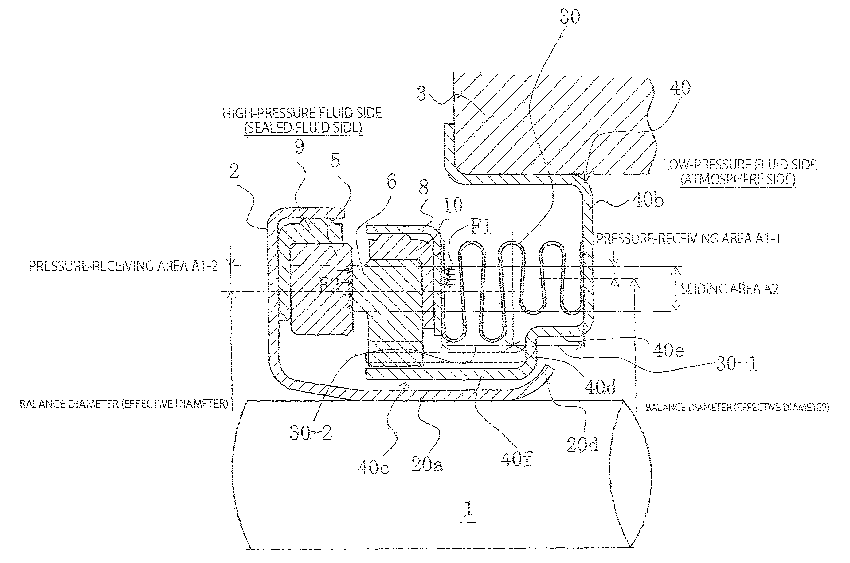
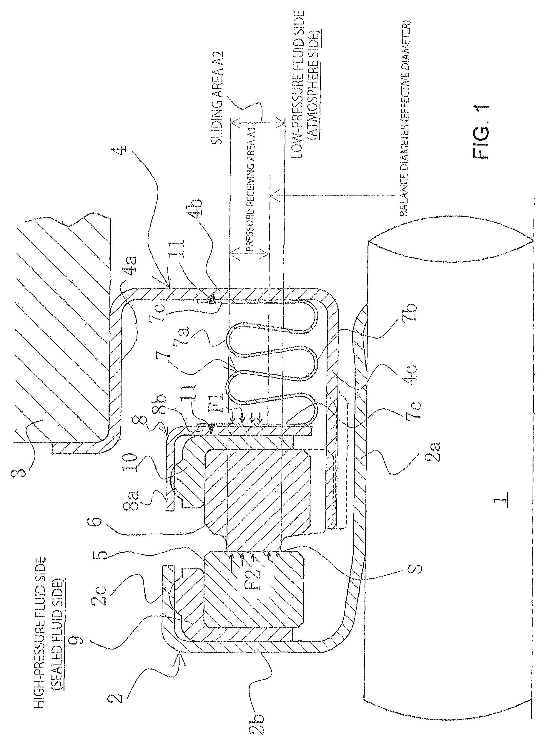
[0043]A description will now be given for a mechanical seal according to a first example of the present invention. The present invention is applied to an inside-type mechanical seal of a format in which a fluid trying to leak from the outer circumference of the sealing face to the inner circumference direction is sealed. In FIG. 1, the left side corresponds to the high-pressure fluid side (sealed fluid side) and the right side corresponds to the low-pressure fluid side (atmosphere side).

[0044]The mechanical seal according to the present invention is a mechanical seal comprising a sleeve 2 fixed to a rotating shaft 1, and a cartridge 4 fixed to a housing 3; a rotation-side sealing ring 5 being provided to the sleeve 2; and a fixed-side sealing ring 6, which slides against the rotation-side sealing ring 5, and a bellows 7 for axially urging the fixed-side sealing ring 6 being provided to the cartridge 4; the mechanical seal being mainly characterized in that: the bellows 7 is made fro...

second example

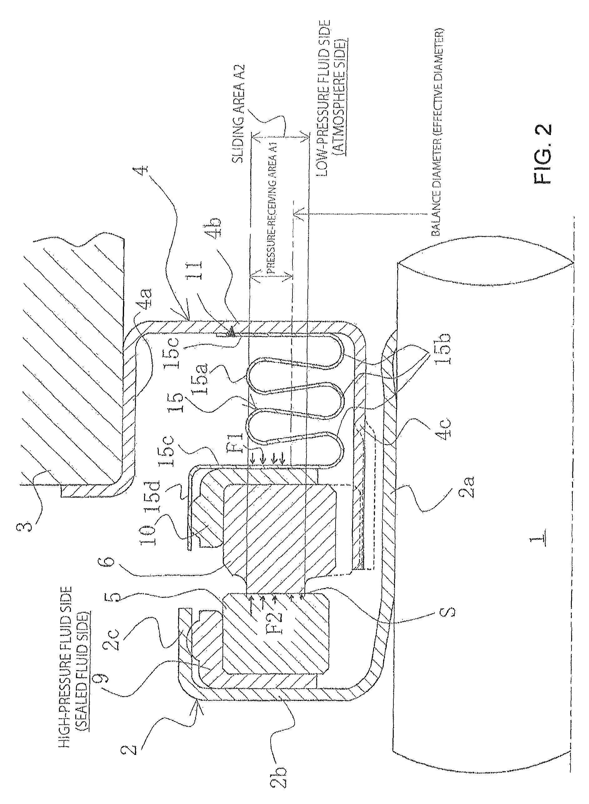
[0056]Next, a description will be given for a mechanical seal according to a second example of the present invention with reference to FIG. 2. The second example, shown in FIG. 2, differs from the first example shown in FIG. 1 in having the metal bellows formed so as to also function as the case. However, other configurations are the same as those in the first example, and descriptions that overlap will not be provided.

[0057]In FIG. 2, a bellows 15 comprises a stretchable bellows part in which crest parts 15a and trough parts 15b are alternately formed, a disc-shaped flange part 15c extending from a trough part 15b of the bellows 15 is provided at each axial end part of the bellows 15, the inner diameter of the flange parts 15c, 15c is formed so as to be substantially the same as or slightly larger than the trough parts 15b of the bellows 15, and the outer diameter of the flange parts 15c is formed so as to be larger than the crest parts 15a of the bellows 15. The flange part 15c of...

third example

[0060]Next, a description will be given for a mechanical seal according to a third example of the present invention with reference to FIG. 3. The third example, shown in FIG, 3, differs from the second example shown in FIG. 2 in that a band is attached on an outer circumference of an outer cylinder part of the metal bellows. However, other configurations are the same as those in the second example, and descriptions that overlap will not be provided.

[0061]In FIG. 3, a band 16 is attached on the outer circumference of the outer cylinder part 15d of the metal bellows 15. The band 16 squeezes the outer cylinder part 15d radially inwards so as to act against the radially outward elastic force of the cup gasket 10. The band 16 comprises, e.g.: a hose-band-type [element] made from a ring-shaped, flat plate capable of elastically deforming and configured so that the diameter is decreased by tightening, by screwing, the circumferential-direction bonding part; a plate-clip-type [element] (one...


PUM


Abstract

To provide a mechanical seal in which degradation or tearing of a bellows does not occur, the spring constant of the bellows is reduced, and the fluctuation in the load due to stretching and contracting of the bellows is reduced. An inside-type mechanical seal includes a sleeve fixed to a rotating shaft, and a cartridge fixed to a housing. A rotation-side sealing ring is provided to the sleeve. A fixed-side sealing ring, which slides against the rotation-side sealing ring, and a bellows for axially urging the fixed-side sealing ring is provided to the cartridge. The bellows is made from a metal; and the metal bellows has one end fixed to a case for holding the fixed-side sealing ring and another end fixed to the cartridge. The plate thickness of the metal bellows is set so as to be smaller than the plate thickness of the case or the cartridge.

Description

Cross Reference to Related Application[0001]This application is a divisional of U.S. application No. 14 / 407,372, filed Dec. 11, 2014, which in turn is a 35 U.S.C. 371 application based on PCT / JP2013 / 076968, filed Oct. 3, 2013.TECHNICAL FIELD[0002]The present invention relates to a mechanical seal used, e.g., as a shaft-sealing device in a pump or the like.BACKGROUND ART[0003]One conventionally known type of a mechanical seal is, as shown in FIG. 7, an inside-format mechanical seal in which a sealed fluid that may leak from the outer circumference of a sealing face to the inner circumference direction is sealed, wherein: an annular rotation-side sealing ring 53 provided, via a sleeve 51 and a cup gasket 52, on the side of a rotating shaft 50 for driving a pump impeller (not shown) on the high-pressure fluid-side, so as to be capable of rotating integrally with the rotating shaft 50; and an annular fixed-side sealing ring 55 provided, via a bellows 57 in a cartridge 56, to a housing 5...

Claims


Application Information

Patent Timeline
Patent Type & Authority Patents(United States)
IPC IPC(8): F16J15/34F16J15/36
CPCF16J15/363F16J15/34F16J15/3448F16J15/3452F16J15/348F16J15/38
Inventor ITADANI, MASATOSHISHINOMIYA, TAKASHIOGAWA, YOSHIHIRO
Owner EAGLE INDS
Why Eureka
Try Eureka