Door impact beam

a technology for impact beams and doors, applied in the field of door impact beams, can solve the problems of tubular cross sections and adversely affect manufacturing costs

Inactive Publication Date: 2012-09-18
BENTELER AUTOMOBILTECHNIK GMBH
View PDF27 Cites 2 Cited by
  • Summary
  • Abstract
  • Description
  • Claims
  • Application Information

AI Technical Summary

Benefits of technology

[0007]The final configuration of the door impact beam is already established by the contour of the metal sheet which has been cut to size, i.e. there is no need for a later manufacturing step. The weight is optimized therefore beforehand. The manufacturing process is more cost-efficient than would be the case when a tubular structure has to be cut to size later.
[0012]The reinforcement plate arranged in the center portion of the door impact beam may conform to the geometry of the center portion and also configured in the form of a rectangle. In this case, the reinforcement plate is spaced from the length sides in the center portion and has a length which corresponds to 40% to 100%, preferably 40% to 70%, of a length of the center portion. A flat contact of the reinforcement plate upon the center portion provides a local reinforcement of the door impact beam at a location where maximum stress is encountered in the event of a side impact. The wall thickness of the metal sheet can be reduced by optimizing the cut and suitable positioning of the reinforcement plate, resulting overall in a weight reduction.

Problems solved by technology

Tubular cross sections have the drawback that in areas in which stress is less they generally have a same cross section as in those areas which encounter maximum stress.
This in turn adversely affects manufacturing costs.

Method used


Image

  • Door impact beam
  • Door impact beam
  • Door impact beam

Examples


Embodiment Construction

[0027]Throughout all the figures, same or corresponding elements may generally be indicated by same reference numerals. These depicted embodiments are to be understood as illustrative of the invention and not as limiting in any way. It should also be understood that the figures are not necessarily to scale and that the embodiments are sometimes illustrated by graphic symbols, phantom lines, diagrammatic representations and fragmentary views. In certain instances, details which are not necessary for an understanding of the present invention or which render other details difficult to perceive may have been omitted.

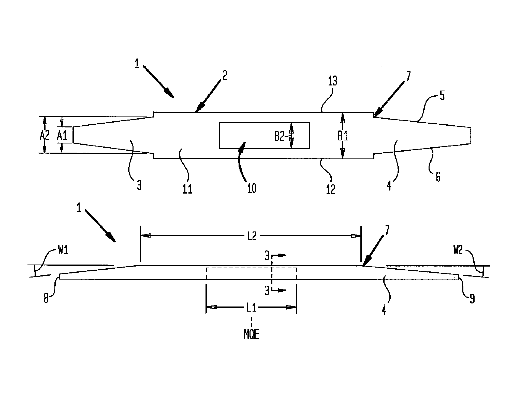
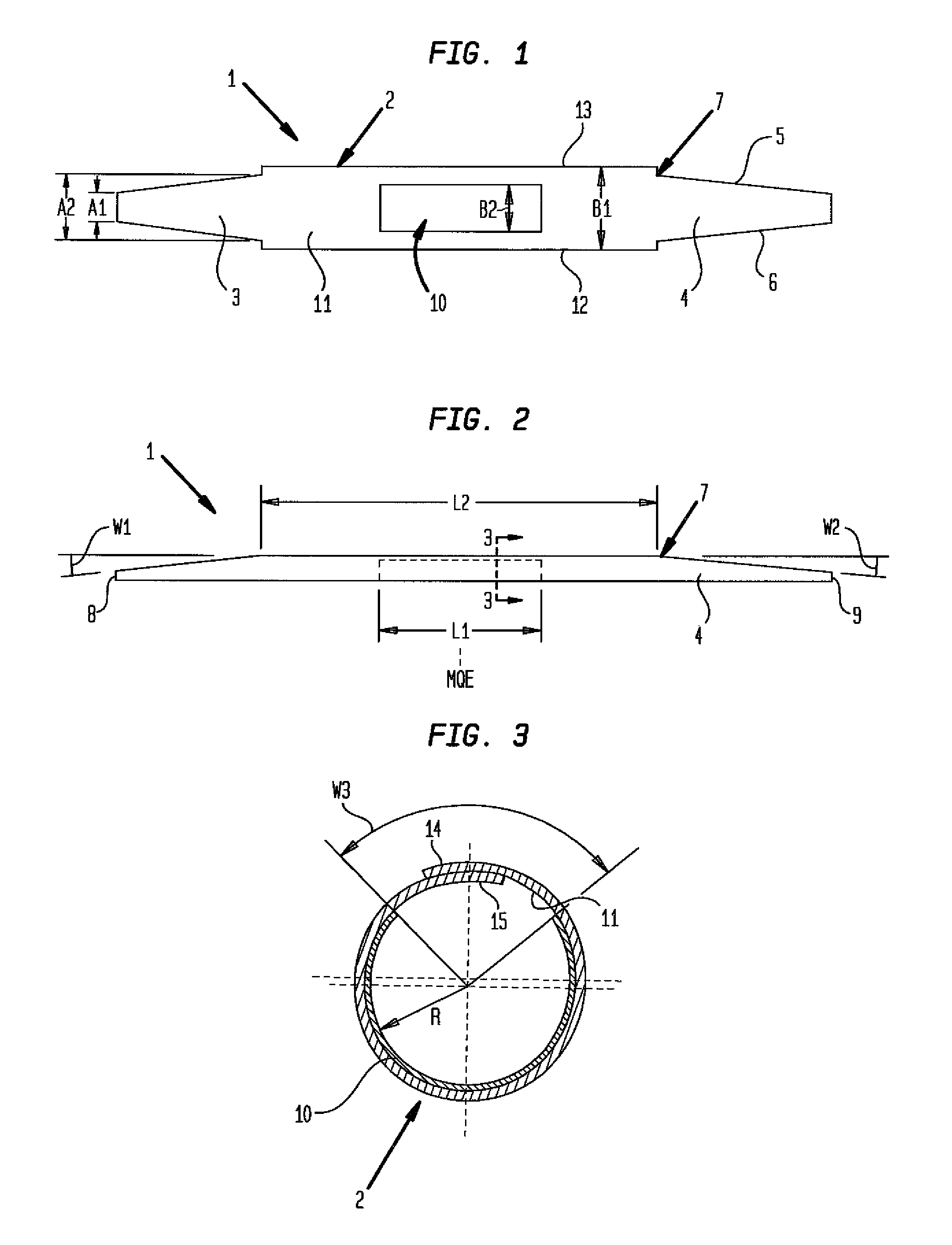
[0028]Turning now to the drawing, and in particular to FIG. 1, there is shown a schematic illustration of a metal sheet, generally designated by reference numeral 1, in its still unformed initial state, for producing a door impact beam. The metal sheet 1 has a center portion 2 of rectangular shape. Adjoining both sides of the center portion 2 in longitudinal direction are tr...


PUM


Abstract

A door impact beam for a motor vehicle includes a formed metal sheet defined by a longitudinal axis and having a tubular cross section which has a closed circumference in a center portion of the metal sheet, and is configured with open circumference at both end portions of the metal sheet which adjoin the center portion in a direction of the longitudinal axis. Each end portion is defined by an opening angle which continuously increases from the center portion to respective ends of the end portions.

Description

CROSS-REFERENCES TO RELATED APPLICATIONS[0001]This application claims the priority of German Patent Application, Serial No. 10 2009 011 378.9, filed Mar. 5, 2009, pursuant to 35 U.S.C. 119(a)-(d), the content of which is incorporated herein by reference in its entirety as if fully set forth herein.BACKGROUND OF THE INVENTION[0002]The present invention relates, in general, to a door impact beam.[0003]The following discussion of related art is provided to assist the reader in understanding the advantages of the invention, and is not to be construed as an admission that this related art is prior art to this invention.[0004]Door impact beams are used in motor vehicles as door reinforcement to protect occupants from injury in the event of an impact from the side, and are typically made of tubes or tubular cross sections, for example extrusion profiles or also press parts. Tubular cross sections have the drawback that in areas in which stress is less they generally have a same cross secti...

Claims


Application Information

Patent Timeline
Patent Type & Authority Patents(United States)
IPC IPC(8): B60J5/00
CPCB60J5/0444B60J5/0445B60R19/42
Inventor BUSCHSIEWEKE, OTTOHITZ, ANDREASPAARE, MIRKO
Owner BENTELER AUTOMOBILTECHNIK GMBH
Why Eureka
Try Eureka