Eureka AIR delivers breakthrough ideas for toughest innovation challenges, trusted by R&D personnel around the world.

Machine tooling with a rotary punch

a technology of installation punches and machine tools, which is applied in the direction of metal-working equipment, metal-working equipment, manufacturing tools, etc., can solve the problems of inability to use a thicker material prior to machining, inability to maintain pressure on the cosmetic surface, and undesirable necessity for machining, so as to reduce the severity of cosmetic marking, reduce the installation force, and reduce the effect of installation pressur

Active Publication Date: 2022-06-07
PENN ENG & MFG CORP
View PDF11 Cites 1 Cited by
  • Summary
  • Abstract
  • Description
  • Claims
  • Application Information

AI Technical Summary

Benefits of technology

The patent text describes a method of installing fasteners using a rotary installation machine. This method reduces the force required for installation, which reduces the likelihood of damaging the receiving panel. It also eliminates the need for secondary installation machines, saving time and money. Overall, the method results in a more efficient and cost-effective installation process.

Problems solved by technology

Frequently clinching fasteners are used in these chassis, which can cause a permanent pressure mark on the cosmetic surface due to the high installation forces involved.
A mark is unacceptable.
The necessity of using a thicker material prior to machining is undesirable as machining time and scrap are significantly increased.
These fasteners have not gained wide acceptance in the field of general hardware fasteners although they have many possible uses.
There is no known automated system for assembling this type of fastener to other manufacturing components.

Method used


Image

  • Machine tooling with a rotary punch
  • Machine tooling with a rotary punch
  • Machine tooling with a rotary punch

Examples


Embodiment Construction

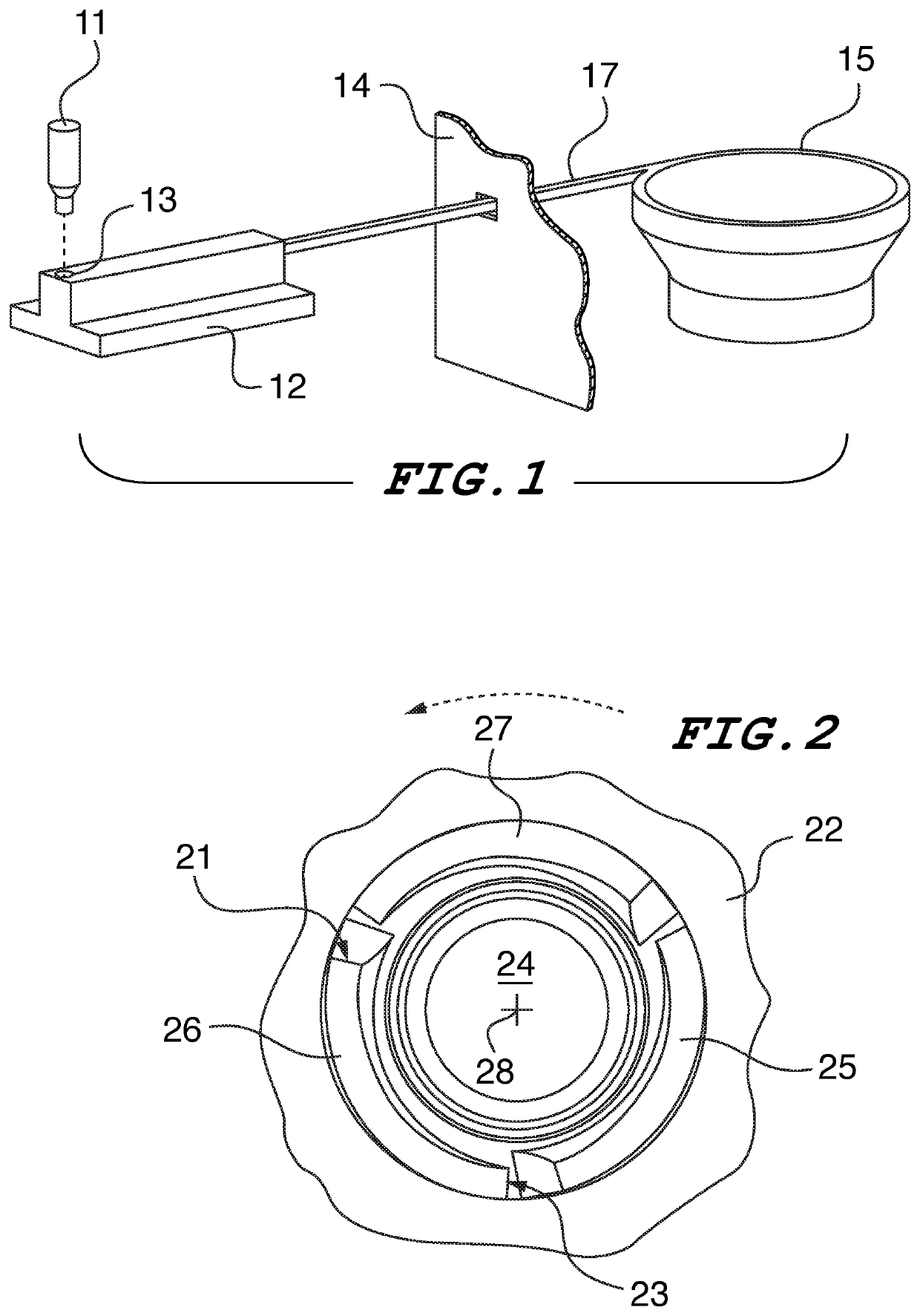
[0025]FIG. 1 illustrates the present system for feeding fasteners directly into a CNC machining center for the purposes of rotary installation. The progression of fasteners from the source bowl to the install punch is as follows:

[0026]1. Parts are poured loosely in bulk into the vibratory feeder bowl 15.

[0027]2. Parts are then fed out of the bowl 15, singulated by an escapement and shuttle, and fed through a flexible feed tube, or a rigid track 17 that passes through a small opening in a machine guard 14.

[0028]3. Next, the single part enters a staging nest 12 where it is positioned on a precise location 13 for pick up by a CNC punch tool such as the tool of the present invention.

[0029]4. Finally, the punch or CNC bed moves to a location where the fastener held by the punch tool is installed.

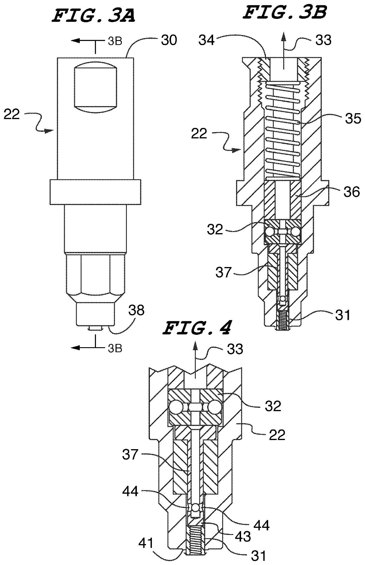
[0030]Referring now to FIG. 2, a bottom plan view of the tip of a rotary displacer punch tool 22 of one embodiment of the invention is shown. In this embodiment, three rotary displacers, 25, 26 a...


PUM

PropertyMeasurementUnit
heightaaaaaaaaaa
axis of rotationaaaaaaaaaa
vacuumaaaaaaaaaa

Abstract

A tooling system has means for applying a vacuum to hold the fastener at the working end of the tool. A cavity in a hollow pusher pin has lateral ports for exclusively providing a airway between the vacuum source and the fastener. In other embodiments of the invention the pusher pin has fastener-gripping jaws in the form of balls moveable within lateral passageways in the pusher pin open into the cavity. The balls are biased inwardly against the fastener by an outer elastic band on the tool body which encircles the pusher pin. When adapted for installing magnetic-release type fasteners, the bottom end of the pusher pin is of reduced diameter for insertion into a magnetic release fastener. The fastener-receiving panel is supported by an anvil having a magnet whereby the fastener is released from the pusher pin as the fastener is pressed into the panel.

Description

RELATED APPLICATIONS[0001]This is a non-provisional patent application related to provisional patent application entitled “Machine Tooling with Rotary Punch and Magnetic Anvil”, Ser. No. 62 / 767,702 filed Nov. 15, 2018 priority from which is hereby claimed.FIELD OF THE INVENTION[0002]This disclosure describes three types of rotary installation punches, and one magnetic release anvil system that enable the use of a CNC machining center to install rotary installation fasteners directly with a CNC machining center.BACKGROUND OF THE INVENTION[0003]Currently for many consumer electronics, a metal chassis is used for aesthetics and mechanical rigidity. These housings can be created in high speed CNC machining center. Once a chassis is cut, it is moved to other locations for assembly of hardware and ultimately finishing by means of anodizing or other cosmetic process. Frequently clinching fasteners are used in these chassis, which can cause a permanent pressure mark on the cosmetic surface ...

Claims


Application Information

Patent Timeline
Patent Type & Authority Patents(United States)
IPC IPC(8): B23P19/00B23P19/06B21J15/32
CPCB23P19/007B23P19/062B21J15/32B23P19/006B23P19/064
Inventor MALONEY, MICHAEL
Owner PENN ENG & MFG CORP
Why Eureka
Eureka Blog
Learn More