Excavator bucket

a bucket and excavating technology, applied in the direction of mechanical machines/dredgers, soil shifting machines/dredgers, constructions, etc., can solve the problems of reducing the thickness of the metal plate for the base wall, limiting the amount of dirt it can carry before reaching the maximum weight limit, etc., to achieve the effect of reducing the thickness of the metal pla

Active Publication Date: 2015-10-01
SPADEBLADE
View PDF29 Cites 2 Cited by
  • Summary
  • Abstract
  • Description
  • Claims
  • Application Information

AI Technical Summary

Benefits of technology

[0030]With the preferred embodiment of a bucket with a convex shaped front section, the thickness of the metal plates for the base wall is preferably reduced because the convex shape of the front section provides structural strength to the bucket.

Problems solved by technology

As the buckets are relatively heavy because they are made of the thick metal plates, there is a limit to the amount of dirt it can carry before the maximum threshold weight limit is reached.
However, collecting dirt with a concave shaped bucket has problems in that collected dirt flowing into the bucket sometimes falls out of the concave shaped bucket.

Method used


Image

  • Excavator bucket
  • Excavator bucket
  • Excavator bucket

Examples


Embodiment Construction

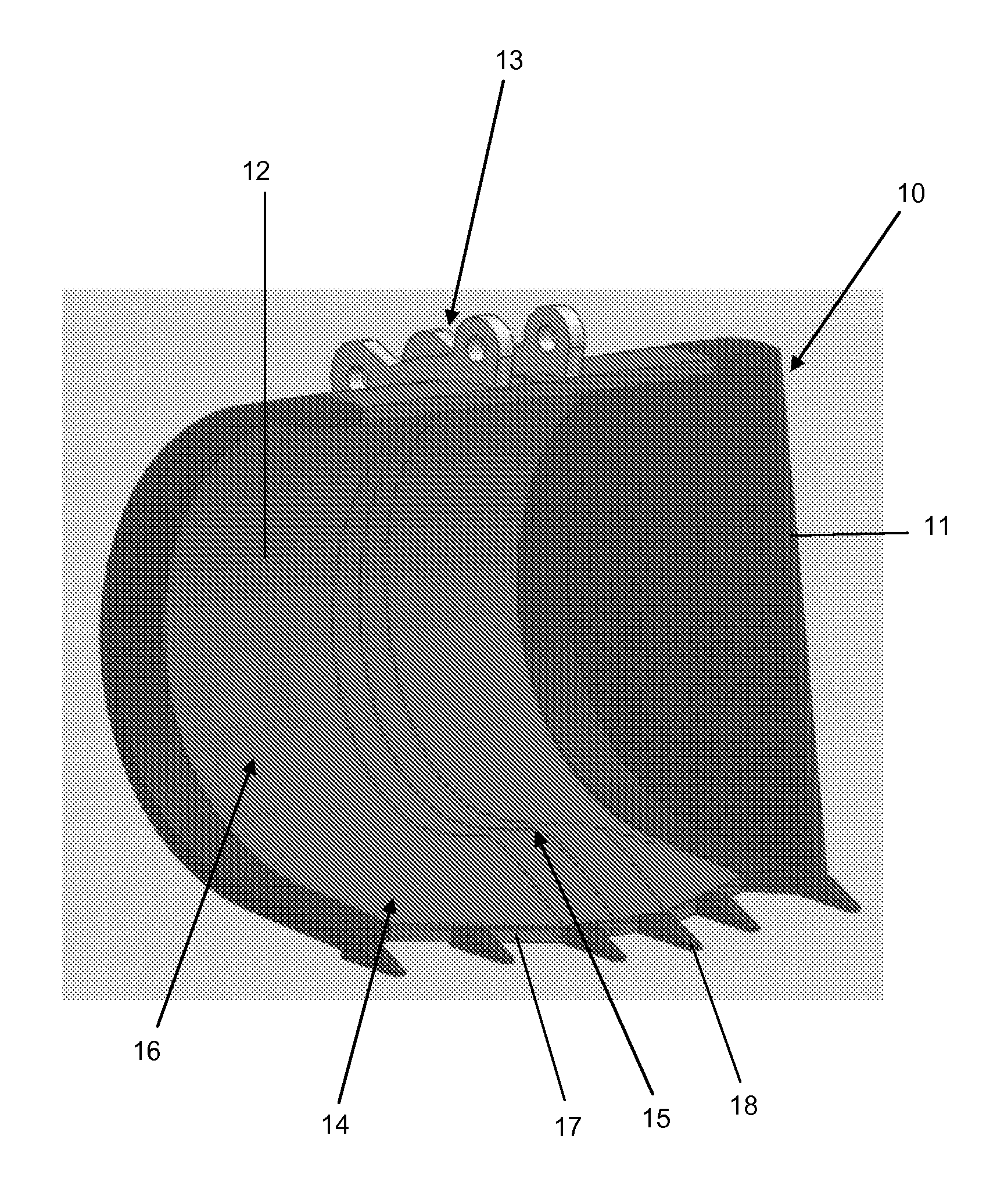
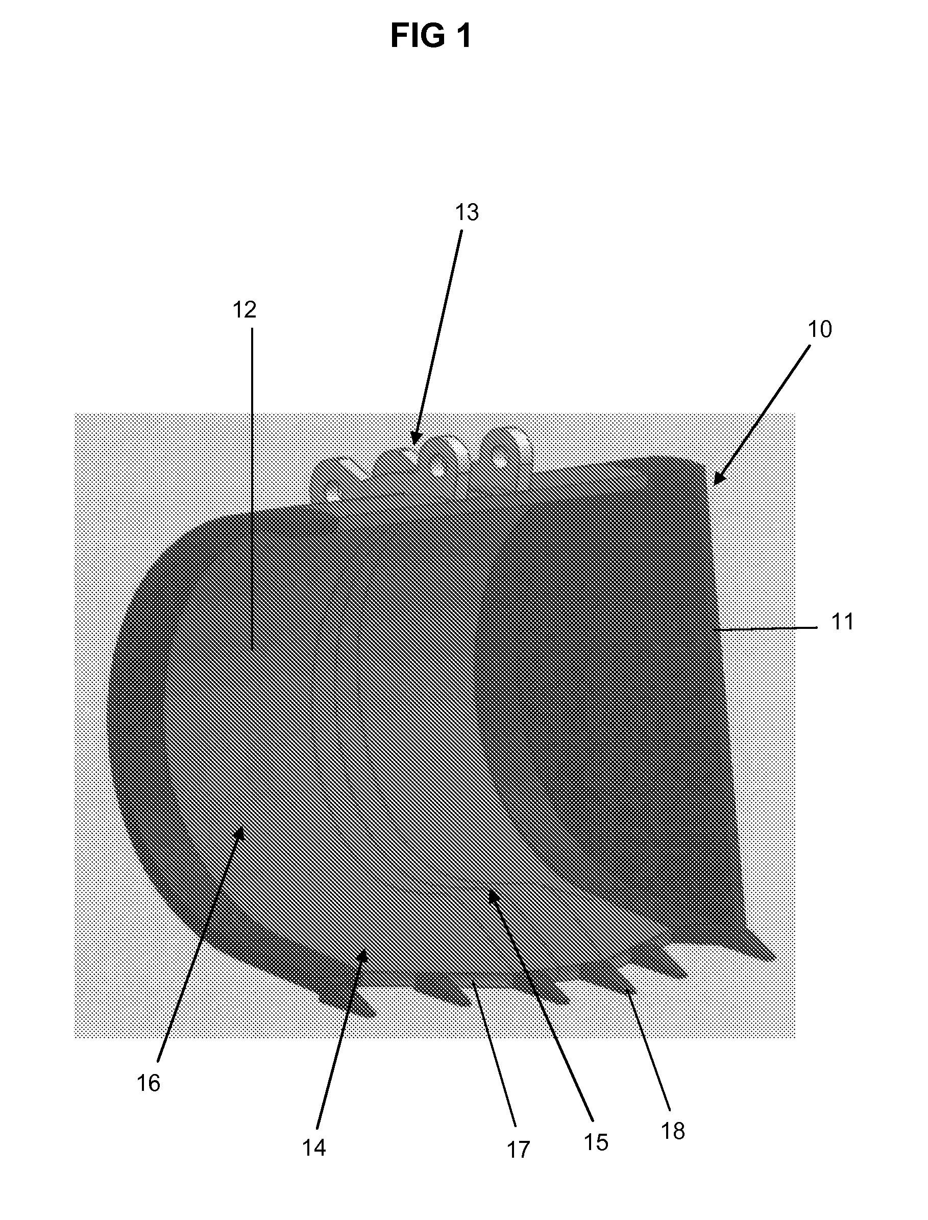
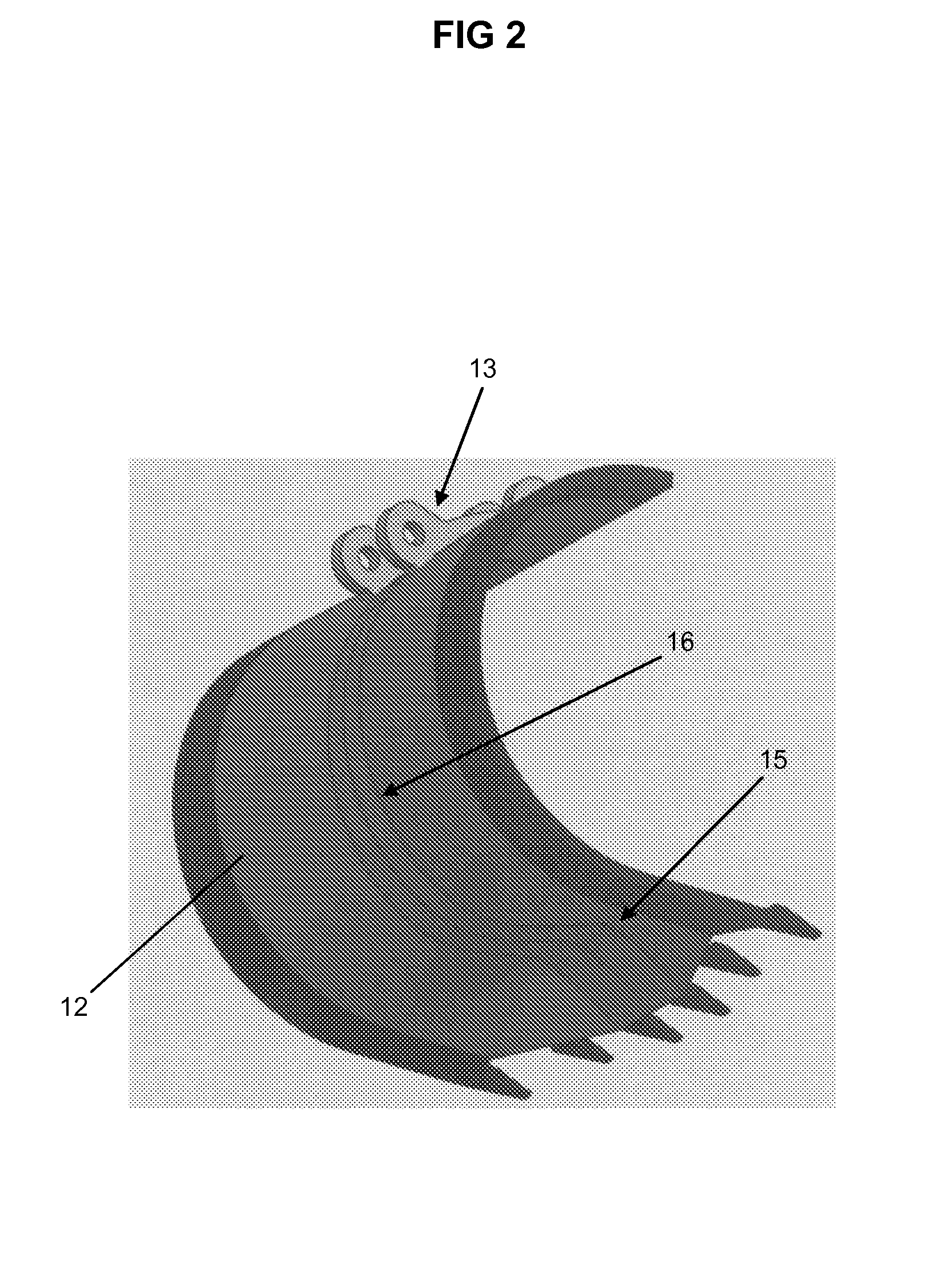
[0036]With reference to the figures, there is shown an excavator bucket 10 with side walls 11, base wall 12 and mounting 13. The base wall 12 has a front section 14 that has a convex or domed shaped portion 15. The convex or domed shaped portion 15 is substantially elongate extending partially across the front section 14 and slopes away towards each of the side walls 11. The base wall 12 also has a concave rear section 16. The leading edge 17 of the front section 14 has a plurality of outwardly protruding teeth 18.

[0037]The mounting 13 attaches to the hydraulically-operated arm of the excavator. With hydraulic rams, the bucket 10 can be tilted upwards and downwards. The hydraulically-operated arm can raise or lower the bucket 10.

[0038]In use the bucket 10 is tilted downward through the actuation of hydraulic rams. The arm of the excavator is lowered so that the teeth 18 penetrate the ground. Dirt passes into the bucket 10 flowing up the front section 14. The dirt is diverted from th...


PUM


Abstract

The invention is directed to a bucket for an excavator or loader and includes a base wall having a side with a substantial or partly concave shape, the side with the substantial or partly concave shape has a front section that is raised, flat or concave and a rear section that has a concave arc. The base wall side has a discontinuous curve from the front section to the rear section. The bucket has two side walls spaced apart by the base wall. The bucket has a mounting mechanism for mounting the bucket to the excavator or loader. The raised, flat or concave front section assists in retaining excavated material within the bucket.

Description

[0001]This application is a National Stage completion of PCT / AU2013 / 001155 filed Oct. 8, 2013, which claims priority from Australian patent application serial no. 2012904381 filed Oct. 8, 2012.FIELD OF INVENTION[0002]The present invention relates to excavator buckets and loader buckets. Reference and comments in the specification to excavator buckets also apply to loader buckets unless otherwise specified.BACKGROUND OF THE INVENTION[0003]Excavator buckets are used by excavators and like vehicles to dig the earth and remove dirt. Conventional excavator buckets have a concave base wall separating two side walls that together form a bucket shape. Many of the excavator buckets have a series of teeth on the leading edge to penetrate the ground.[0004]Because of the impact forces associated with penetrating and digging the ground, the excavator buckets have walls of thickened metal plates to withstand these forces. The hydraulic-operated arms of the excavators can lift loaded buckets up to...

Claims


Application Information

Patent Timeline
Patent Type & Authority Applications(United States)
IPC IPC(8): E02F3/40
CPCE02F3/40
Inventor HALL, DAVID
Owner SPADEBLADE
Why Eureka
Try Eureka