Heat exchanger assembly having a distributor tube retainer tab

a technology of distributor tubes and heat exchangers, which is applied in the direction of heat exchanger casings, heat exchange apparatus, light and heating apparatus, etc., can solve the problems of retainer tabs, reduce the vibration of distributor tubes, reduce audible noise, and prevent damage to the ends

Inactive Publication Date: 2017-02-28
MAHLE INT GMBH
View PDF42 Cites 0 Cited by
  • Summary
  • Abstract
  • Description
  • Claims
  • Application Information

AI Technical Summary

Benefits of technology

[0009]The retainer tab provides the advantages of reducing the excessive vibrations of the distributor tube to reduce audible noise and to prevent damage to the ends of the refrigerant tubes; not requiring a braze joint inside the manifold, which would be difficult or impossible to check, to permanently engage the distributor tube; holding the distributor tube in close contact with the inside wall of the header, thereby avoiding interference with the refrigerant tubes; and maintaining the distributor tube in the proper centered location, in applications where the manifold is bent, by restraining the distributor tube during the bending process.

Problems solved by technology

The retainer tab may be interference fitted into the retainer slot.

Method used


Image

  • Heat exchanger assembly having a distributor tube retainer tab
  • Heat exchanger assembly having a distributor tube retainer tab
  • Heat exchanger assembly having a distributor tube retainer tab

Examples


Embodiment Construction

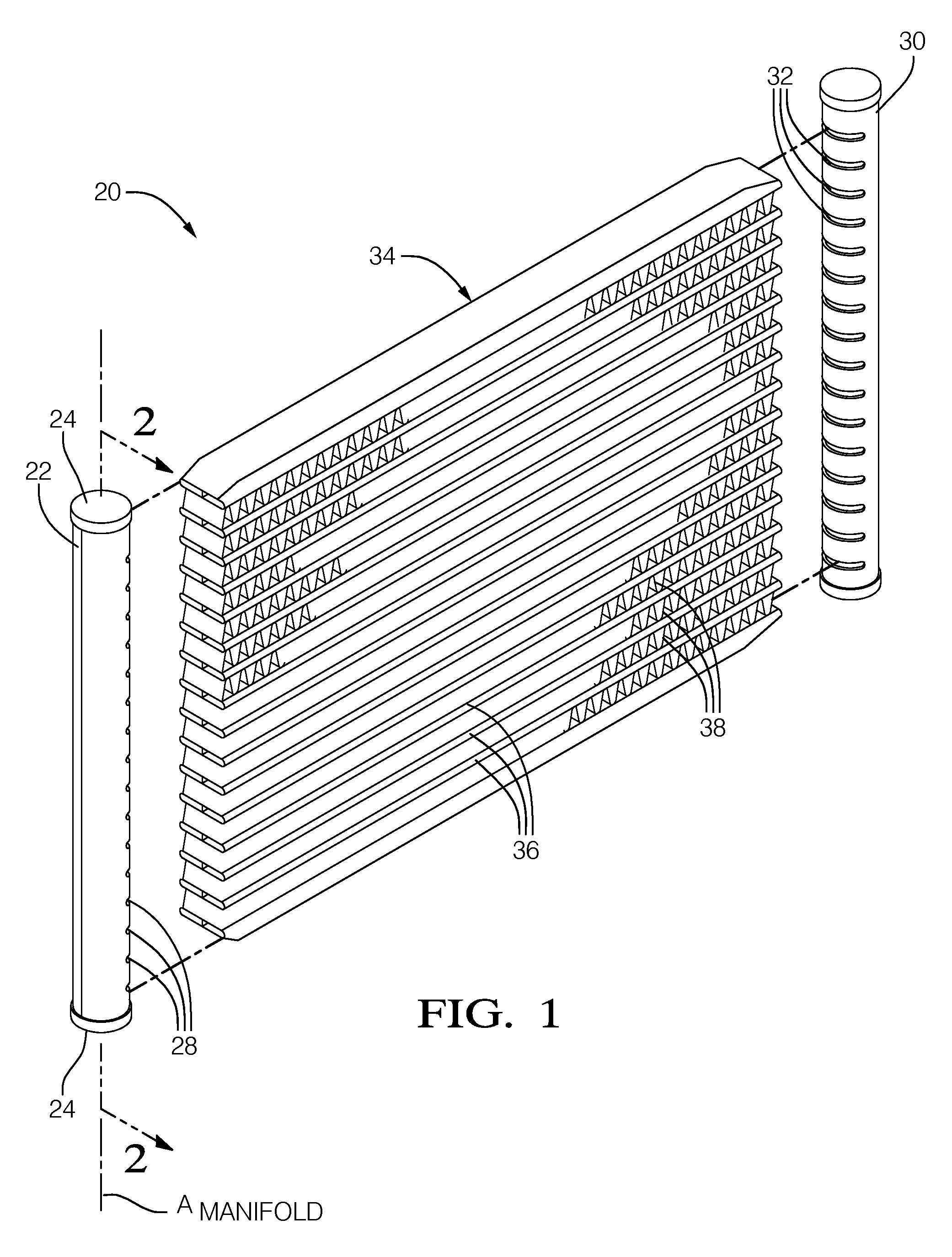
[0015]Referring to the Figures, wherein like numerals indicate corresponding parts throughout the several views, is an exemplary embodiment of a heat exchanger assembly 20 for transferring heat between a first fluid and a second fluid is generally shown. The first fluid of the exemplary embodiment may be that of a two phase refrigerant and the second fluid may be that of a stream of ambient air. It should be appreciated that other first and second fluids may be used.

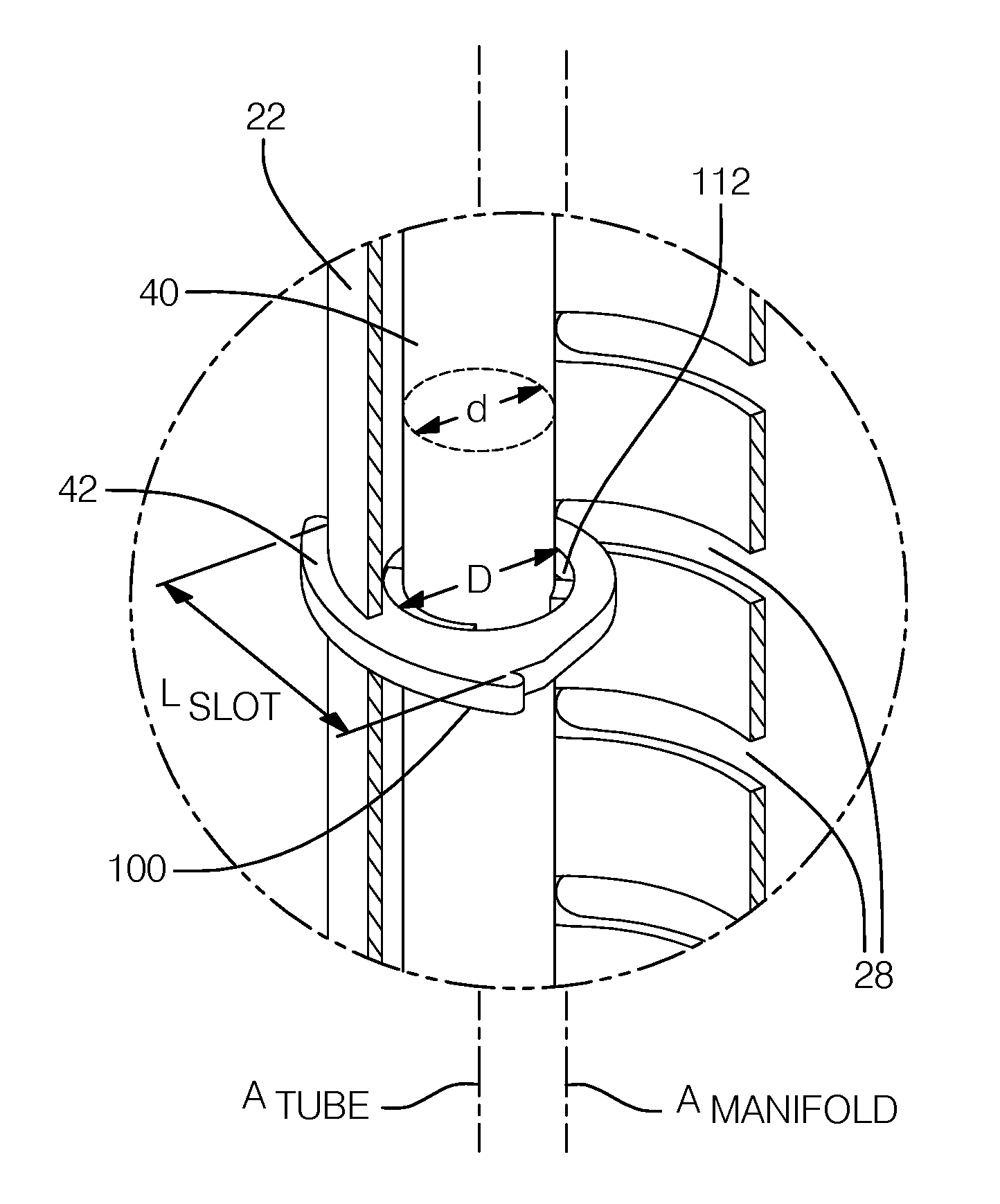
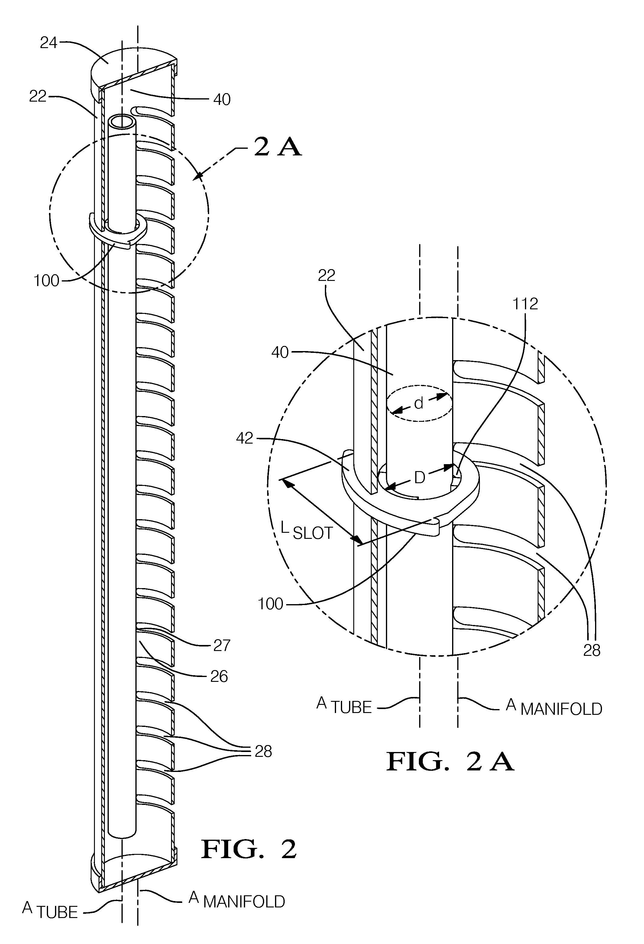
[0016]Shown in FIG. 1 is a heat exchanger assembly 20 having a first manifold 22 extending along a manifold axis Amanifold between first manifold ends 24. The first manifold 22 has an interior surface 26 defining an interior chamber 27, which is best shown in FIG. 2. The first manifold 22 presents a plurality of first tube slots 28 spaced apart from one another along the axis Amanifold. The heat exchanger assembly 20 also includes a second manifold 30 extending in a spaced and substantially parallel relationship with the...


PUM


Abstract

A heat exchanger assembly having an insertable distributor tube retainer tab configured to position and retain a distributor tube disposed within a first manifold extending along an axis Amanifold. The first manifold includes a manifold wall having an interior surface defining an interior chamber, an exterior surface opposite of the interior surface, and a retainer slot connecting the interior surface and the exterior surface. The retainer slot extends substantially transverse to the manifold axis Amanifold. The retainer tab is inserted through the retainer slot and includes a first tab portion disposed within the interior chamber and a second tab portion 104 engaged to the wall of the first manifold, and may also include a third tab portion engaged to a width surface of the retainer slot. The retainer tab includes a tab opening configured to engage and maintain the distributor tube within the predetermined position.

Description

CROSS-REFERENCE TO RELATED APPLICATION[0001]This application claims the benefit of U.S. Provisional Patent Application Ser. No. 61 / 581,180 for a DISTRIBUTOR TUBE RETAINER TAB, filed on Dec. 29, 2011, which is hereby incorporated by reference in its entirety.TECHNICAL FIELD OF INVENTION[0002]The present invention relates to a heat exchanger assembly having a distributor tube; more particularly, to a heat exchanger assembly having a distributor tube retainer tab configured to position and retain a distributor tube in a predetermined position.BACKGROUND OF INVENTION[0003]Air conditioning and heat pump systems for residential and commercial applications are known to employ modified automotive heat exchanger assemblies because of their high heat transfer efficiency, durability, and relatively ease of manufacturability. A typical automotive heat exchanger assembly includes an inlet manifold, an outlet manifold, and a plurality of extruded multi-port refrigerant tubes hydraulically connect...

Claims


Application Information

Patent Timeline
Patent Type & Authority Patents(United States)
IPC IPC(8): F28F9/013F28F9/02
CPCF28F9/0131F28F9/0273F28F9/027F28F9/0246
Inventor SAMUELSON, DAVID E.
Owner MAHLE INT GMBH
Why Eureka
Try Eureka