Clamp and spike for flexible conduit

a flexible conduit and spike technology, applied in the direction of pipe connection arrangements, spraying apparatus, liquid spraying apparatus, etc., can solve the problems of limited amount of water available, inability to insert the hollow spike into the existing water conduit, and difficulty in ensuring the safety of the pipe,

Active Publication Date: 2017-03-07
NAT DIVERSIFIED SALES
View PDF8 Cites 0 Cited by
  • Summary
  • Abstract
  • Description
  • Claims
  • Application Information

AI Technical Summary

Benefits of technology

[0007]In a first aspect, the invention is a clamp and spike combination for use in conjunction with a flexible conduit that has a standard diameter having a magnitude of a first distance. In the preferred embodiment, the combination comprises a spike including an inlet rod with a sharpened tip for penetration into the conduit. An outlet rod is connected to the inlet rod, the outlet rod having a barbed tip for attachment to a tube. A bore extends through the rods from the sharpened tip to the barbed tip, whereby the spike provides a channel for the passage of fluid. The combination further has a clamp including two legs extending substantially parallel with each other and spaced apart from each other by a maximum spacing having a second distance. The second distance is substantially equal to the first distance, by which it is meant herein that the second distance is sized to snugly receive a conduit of standard diameter having a magnitude of a first distance. An apex portion connects the two legs to each other so that the clamp is shaped substantially in the form of an inverted “U.” The apex portion defines an opening sized to receive the inlet rod of the spike, whereby the inlet rod of the spike is receivable through the opening in the apex portion to penetrate a received conduit. Thus, the clamp, once mounted on a conduit, advantageously provides a fixed and secure opening above the conduit. A user may safely insert a sharpened portion of the spike through the opening and safely force the spike into the conduit without concern that the spike will slip off the rounded conduit and physically injure the hand holding the conduit. Once the spike has safely penetrated the conduit, the clamp provides a support against bending and removal of the spike from the conduit.
[0009]In another aspect of the combination, each leg of the clamp includes, at a terminal end of the leg opposite the apex, a foot extending towards the foot on an opposite leg so that the two feet are separated from each other by a third distance that is smaller than the second distance, and thus also smaller than the standard diameter of a received conduit, whereby a standard diameter conduit received between the two legs is restrained against removal from the clamp by the two feet. This has the advantage of securely fixing the clamp in relation to the conduit and spike at all material times during installation and use. Also preferred, the clamp has a first elongate width and further includes two opposing shaping surfaces, each shaping surface attached to a leg and having a second elongate width that is smaller than the first width, the shaping surfaces being spaced apart from each other by a fourth distance smaller than the second distance, whereby a conduit of standard diameter received between the two legs is compressed out of circular shape by the shaping surfaces. Preferably, the fourth distance is not more than 90 percent of the second distance, and the second width is not more than 30 percent of the first width.

Problems solved by technology

However, the supply of water has remained constant, or has declined.
Therefore, ever more systems are being developed to apply the limited amount of water available.
One of the problems encountered in converting an existing water distribution system to be capable of low flow bubbler irrigation is that inserting the hollow spike into an existing water conduit is attended with considerable difficulty.
First, it is difficult to apply pressure to a sharpened tip of a typical spike because a radially outwardly extending barbed tip on an opposite external end of the spike makes it difficult for a user to gain a suitable grip on the body of the spike without injuring himself.
Second, the sharpened tip of the spike has a tendency to slip off the rounded conduit surface when pressure is applied, thereby introducing the danger of injury to the installer via the sharpened tip.
Third, if the sharpened tip of the spike is not sufficiently sharp, pressure applied to the spike has a tendency to buckle the surface of the water conduit rather than pierce into it.
However, although a stiffer pipe has a smaller tendency to buckle, such pipes are more difficult to pierce and therefore increase the tendency of the spike to slide off the rounded conduit surface and potentially injure the installer.
Fourth, once the spike is inserted into a conduit, any bump or knock against the spike tends to damage the seal that results between spike and conduit so that a leak tends to develop.

Method used


Image

  • Clamp and spike for flexible conduit
  • Clamp and spike for flexible conduit
  • Clamp and spike for flexible conduit

Examples


Embodiment Construction

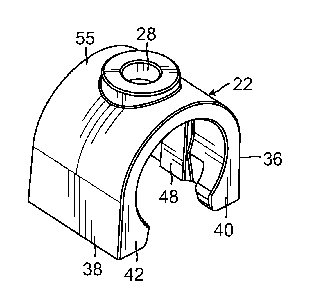
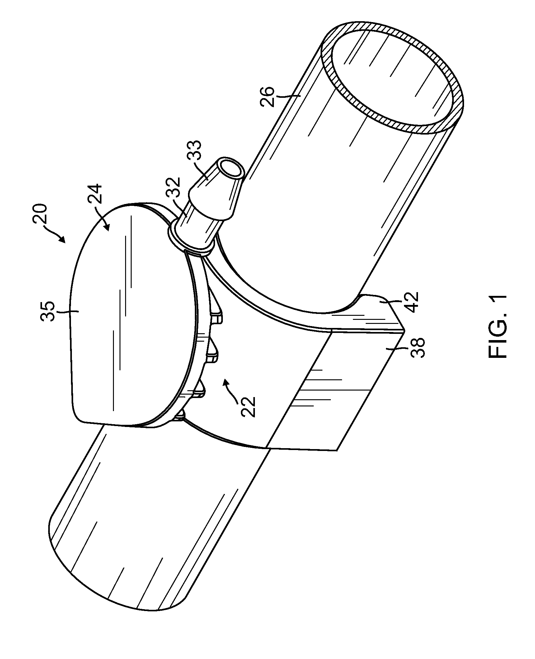
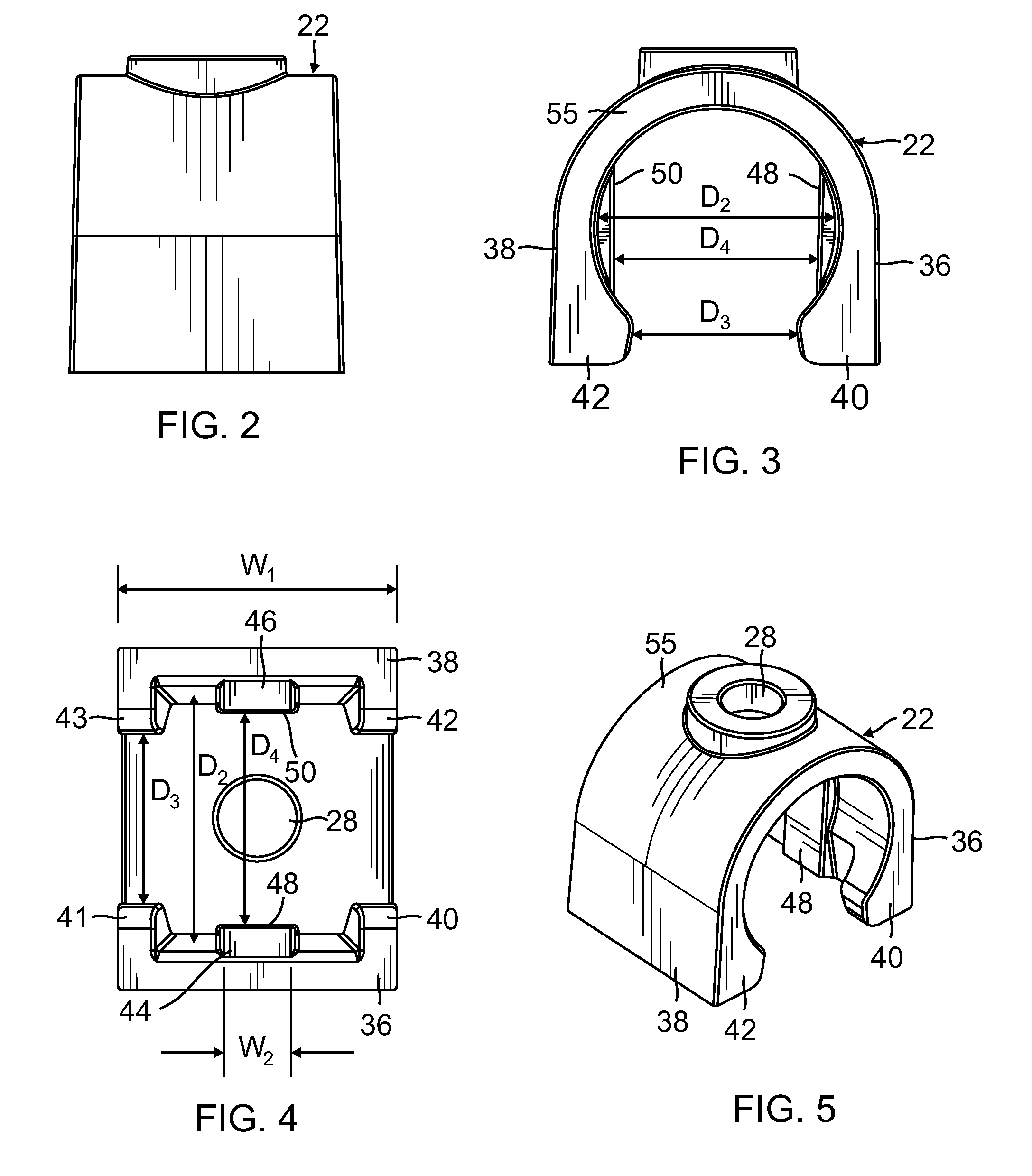
[0026]With reference to the drawings, a preferred embodiment of a clamp and spike combination 20 having features of the present invention is described. FIG. 1 exemplifies the final configuration of the novel clamp 22 and spike 24 as used in combination 20 under the system and method of the present invention. Both clamp and spike are seen in conjunction with a water conduit 26, into which a portion of the spike 24 has been inserted through an opening in the clamp, while the clamp 22 has been mounted on the conduit as described herein below.

[0027]With reference to the drawings, the preferred configuration of the spike 24 of the present invention (best seen in FIGS. 9 and 10) includes a hollow inlet rod 30 with a sharpened tip 31 adapted for penetrating or expanding a hole in a water conduit 26. The spike also includes a hollow outlet rod 32 (FIGS. 1 and 6) with a barbed tip 33, the outlet rod preferably extending at a substantially right angle to the inlet rod 30. Substantially, in th...


PUM

PropertyMeasurementUnit
diameteraaaaaaaaaa
angleaaaaaaaaaa
diameteraaaaaaaaaa

Abstract

A clamp and spike combination for use in conjunction with a flexible conduit, comprising a spike including an inlet rod with a sharpened tip for penetration into the conduit, an outlet rod connected to the inlet rod, the outlet rod having a barbed tip for attachment to a tube. The bore extends through the rods from the sharpened tip to the barbed tip, whereby the spike provides a channel for the passage of fluid. Further included, a clamp including two legs extending substantially parallel with each other and spaced apart from each other by a distance, an apex portion connecting the two legs to each other so that the clamp is shaped substantially in the form of an inverted “U”; and an opening in the apex portion, the opening being sized to receive the inlet rod of the spike.

Description

BACKGROUND[0001]The present invention relates to a device and method for facilitating the insertion of a hollow spike into a flexible conduit.[0002]In recent years, the demand for water to irrigate gardens and public spaces has grown exponentially. However, the supply of water has remained constant, or has declined. Therefore, ever more systems are being developed to apply the limited amount of water available. One such system is the “low flow” system which takes water along a ¼ inch tube to, for example, a bubbler and / or to another low flow emitter such as a micro sprayer, which is an outlet adapted to discharge water directly at the root of a plant with a smaller coverage diameter than the average irrigation sprinkler. The advantages of such a system include the fact that water conveyance efficiency is near 100 percent because wind and evaporation are denied their usual effect on water loss. This may provide for a shortened required time of irrigation, and thus reduces power costs...

Claims


Application Information

Patent Timeline
Patent Type & Authority Patents(United States)
IPC IPC(8): F16L41/06F16L47/34
CPCF16L41/065F16L47/345
Inventor NOURIAN, DANIEL
Owner NAT DIVERSIFIED SALES
Why Eureka
Try Eureka