
LED lighting apparatus with improved heat radiation property

a technology of heat radiation property and led lighting, which is applied in the direction of lighting and heating apparatus, point-like light sources, semiconductor devices for light sources, etc., can solve the problems of reduced driving performance and reliability of driving units, reduced light emission properties and large number of additional circuits, so as to improve the heat radiation property of leds, improve the arrangement of led groups and driving units, and improve the light emission characteristic and brightness of leds

Active Publication Date: 2017-03-07
SILICON WORKS CO LTD
View PDF15 Cites 1 Cited by
  • Summary
  • Abstract
  • Description
  • Claims
  • Application Information

AI Technical Summary

Benefits of technology

The patent is for an LED lighting apparatus that improves heat radiation, brightness, and driving performance. It arranges LED groups with a driving unit to improve heat dissipation. It also determines the positions of LED groups based on heat values to improve heat radiation. Overall, the patent provides technical solutions to improve the performance and reliability of LED lighting apparatuses.

Problems solved by technology

Since the LED is driven by a current, a lighting apparatus using the LED as a light source requires a large number of additional circuits for current driving.
Thus, the driving unit may be positioned in the environment which is not suitable for heat radiation.
When the heat radiation is not smoothly performed due to such an environment, the driving performance and reliability of the driving unit may be reduced.
For such reasons, the light emission property and brightness of the LEDs may be degraded, and the entire driving performance and reliability of the lighting apparatus may be degraded.

Method used


Image

  • LED lighting apparatus with improved heat radiation property
  • LED lighting apparatus with improved heat radiation property
  • LED lighting apparatus with improved heat radiation property

Examples


Embodiment Construction

[0022]Hereafter, exemplary embodiments of the present invention will be described in detail with reference to the accompanying drawings. The terms used in the present specification and claims are not limited to typical dictionary definitions, but must be interpreted into meanings and concepts which coincide with the technical idea of the present invention.

[0023]Embodiments described in the present specification and configurations illustrated in the drawings are preferred embodiments of the present invention, and do not represent the entire technical idea of the present invention. Thus, various equivalents and modifications capable of replacing the embodiments and configurations may be provided at the point of time that the present application is filed.

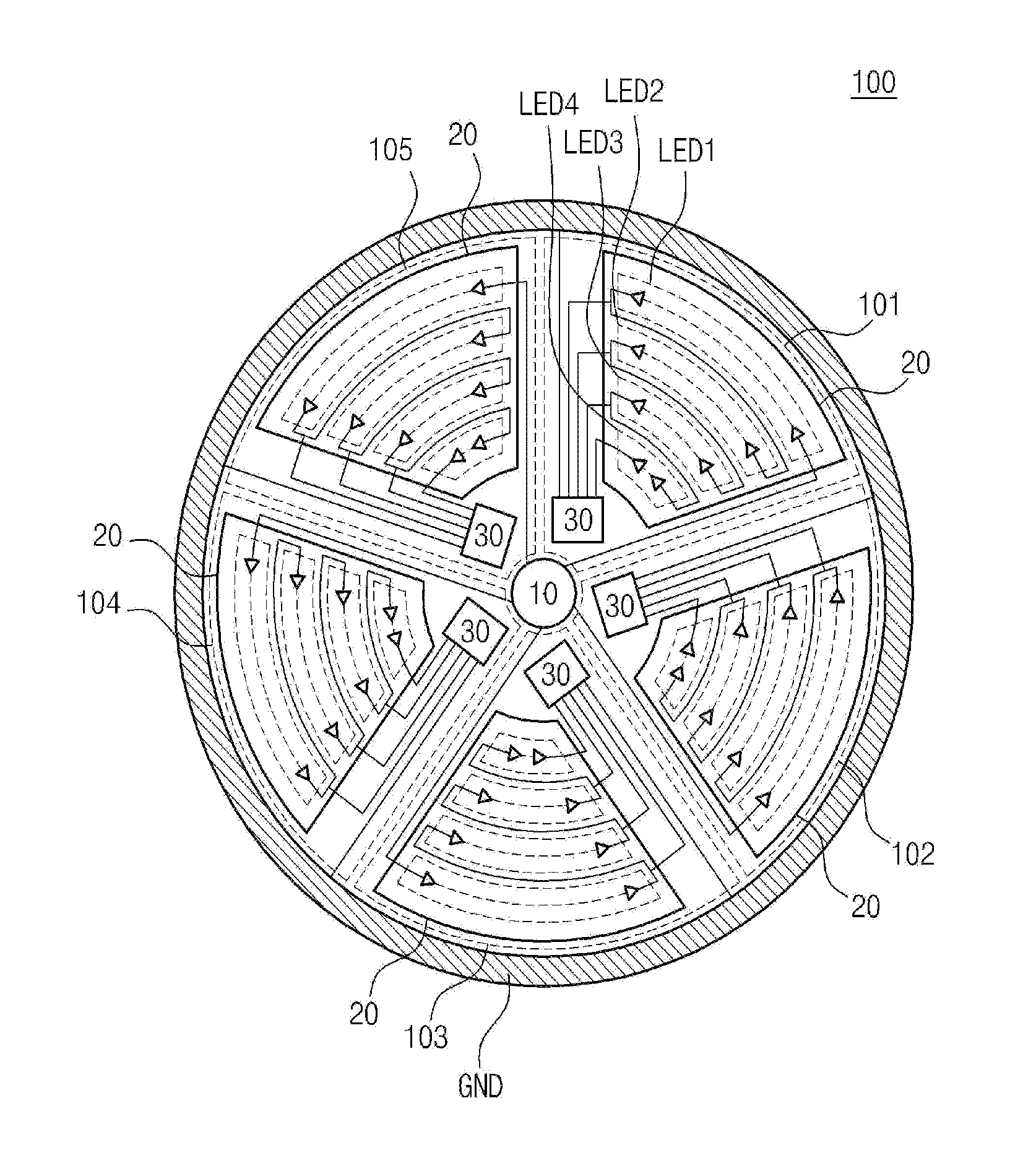
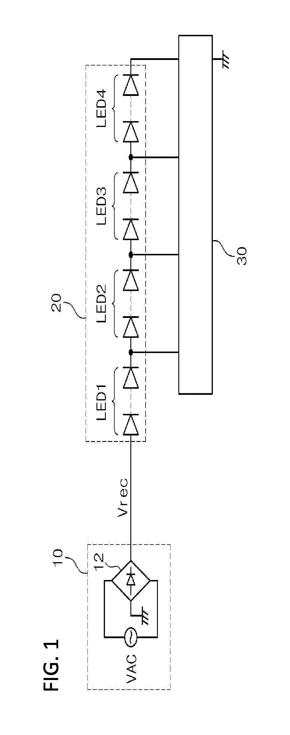
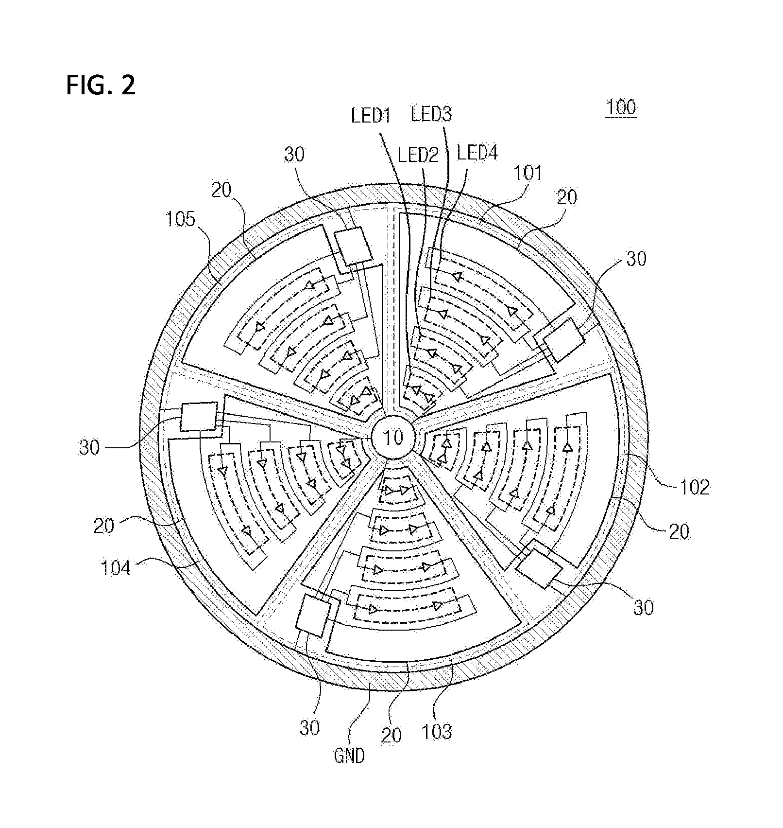
[0024]FIG. 1 is a diagram schematically illustrating an LED lighting apparatus with an improved heat radiation property in accordance with an embodiment of the present invention.

[0025]The LED lighting apparatus with an improved heat ra...


PUM


Abstract

Provided is an LED lighting apparatus with an improved heat radiation property, which is capable of effectively radiating heat generated therein. The LED lighting apparatus may include: a light source unit comprising a plurality of LED groups each having one or more LEDs; and a driving unit configured to provide a current path corresponding to light emission of the light source unit. The light source unit and the driving unit may be arranged on the same substrate so as to be separated from each other. Among the plurality of LED groups, the LED group having the largest heat value may be arranged farthest away from the driving unit, compared to the other LED groups. Through the above-described arrangement, the heat radiation property of the LED lighting apparatus can be improved.

Description

BACKGROUND[0001]1. Technical Field[0002]The present disclosure relates to an LED lighting apparatus, and more particularly, to an LED lighting apparatus with an improved heat radiation property, which is capable of effectively radiating heat generated therein.[0003]2. Related Art[0004]In order to reduce energy, a lighting apparatus is designed to use a light source having high light emission efficiency based on a small amount of energy. Recently, an LED has been used as a representative light source of the lighting apparatus. The LED is differentiated from other light sources in terms of various aspects such as energy consumption, lifetime, and light quality.[0005]Since the LED is driven by a current, a lighting apparatus using the LED as a light source requires a large number of additional circuits for current driving.[0006]In order to solve the above-described problem, an AC direct-type lighting apparatus has been developed to provide an AC voltage to the LED.[0007]The AC direct-t...

Claims


Application Information

Patent Timeline
Patent Type & Authority Patents(United States)
IPC IPC(8): H05B37/00F21V29/10H05B33/08F21Y101/00H05B44/00
CPCF21V29/10H05B33/0824H05B33/0845F21Y2101/00F21K9/00F21V19/001F21V23/003F21Y2115/10H05B45/44H05B45/10H05B45/18H05B45/56
Inventor KIM, YONG GEUNLEEAN, KI CHULJO, EUN JIRA, YUN HEE
Owner SILICON WORKS CO LTD
Learn More