
LED package and method for manufacturing the LED package

a technology of led packages and led tubes, applied in the field of led packages, can solve problems such as the affect of the optical performance of the led package, and achieve the effects of improving brightness, improving optical performance, and improving luminous flux

Active Publication Date: 2017-03-14
LUMILEDS
View PDF24 Cites 0 Cited by
  • Summary
  • Abstract
  • Description
  • Claims
  • Application Information

AI Technical Summary

Benefits of technology

This patent describes an LED package with improved optical performance and a method to manufacture it. The package has an optical element and cover that can be arranged and aligned with respect to the LED, and manufacturing tolerances can be compensated by the same reference. The package is cost-effective and can be manufactured using existing manufacturing machines. Additional parts of the package can have marks to further improve accuracy. The LED package can be easily connected to a housing, such as for a headlight or taillight in a motor vehicle. The "technical effects" of this patent are improved optical performance and alignment accuracy of LED packages.

Problems solved by technology

It is a disadvantage of such kind of a LED package that in more demanding arrangements, when additional parts, like optical elements or covers, are provided, the optical performance of the LED package may be affected.

Method used


Image

  • LED package and method for manufacturing the LED package
  • LED package and method for manufacturing the LED package
  • LED package and method for manufacturing the LED package

Examples


Embodiment Construction

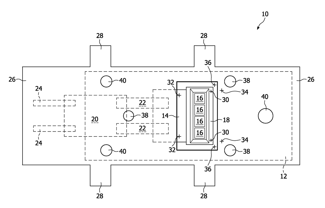
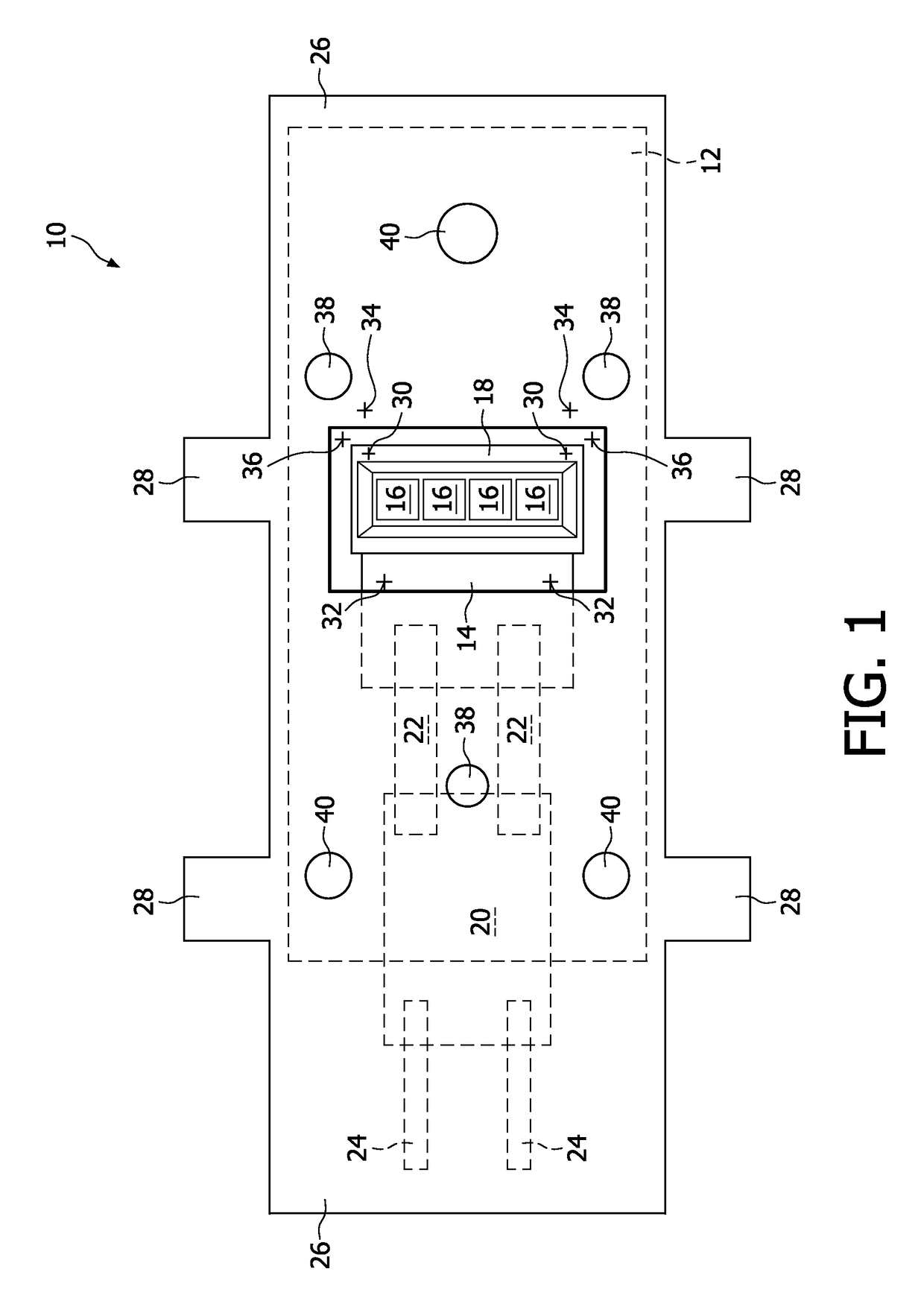
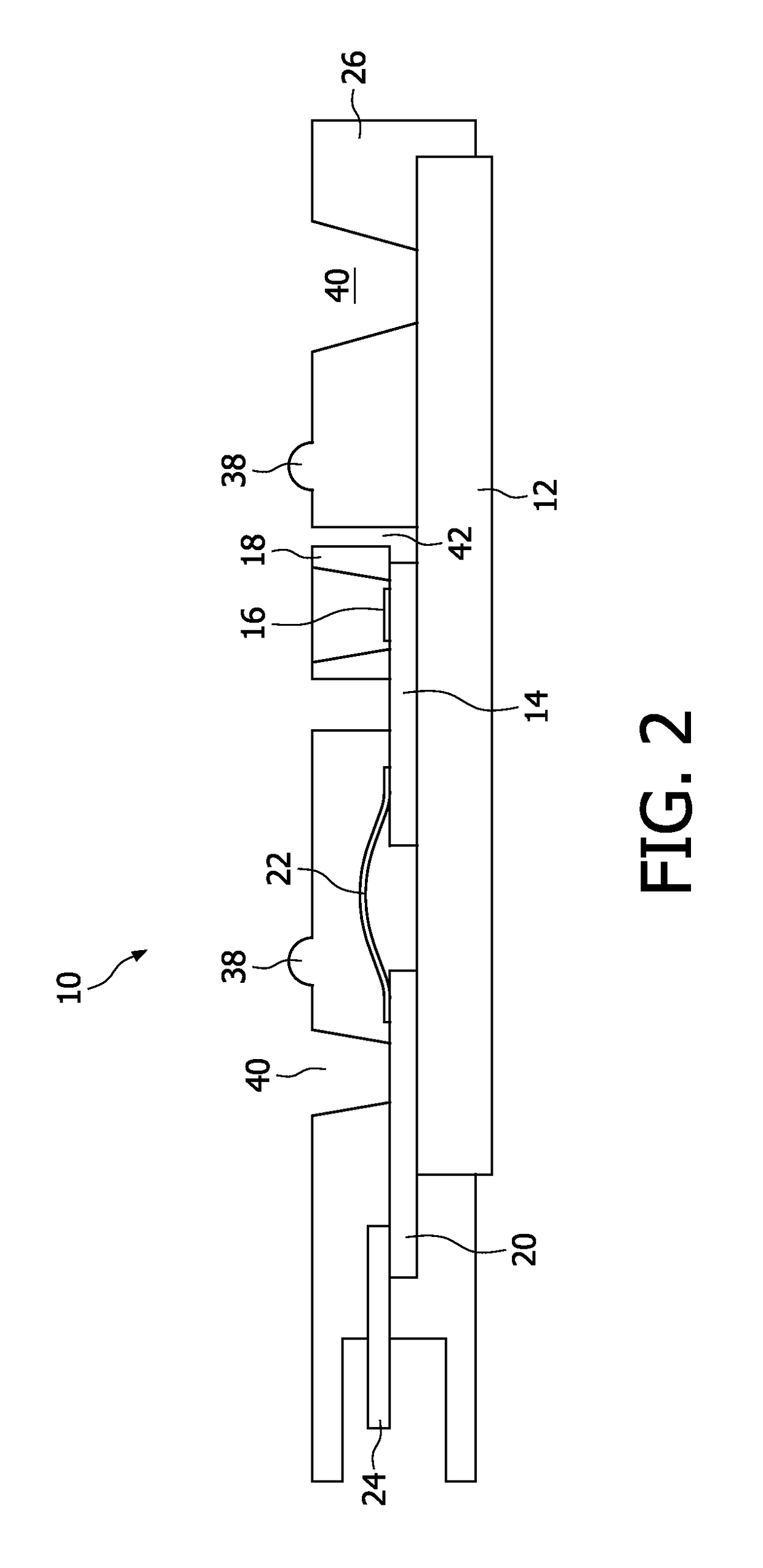
[0018]The LED package 10 illustrated in FIG. 1 comprises a heat sink 12, which may be a copper plate or the like. A substrate 14 is thermally and mechanical connected to the heat sink 12. Four LEDs 16 arranged in a line are fixed to the substrate 14. The LEDs 16 are surrounded by an optical element 18, which may be a collimator comprising a reflective coating for collecting and guiding light emitted by the LEDs 16.

[0019]The optical element 18 is aligned in close vicinity to the LEDs 16. Preferably the optical element 18 comprises a material of high specular or diffuse reflectivity and a high temperature resistance. The coefficient of reflection may be ≧85%, preferably ≧90% and most preferred ≧95%. This material may comprise a good long term stability above 150° C. A high temperature plastics material such as LCP filled with TiO2 or Al2O3 particles may be used as material with a high diffuse reflectivity.

[0020]Further a printed circuit board (PCB) 20 is provided to control the LEDs 1...


PUM


Abstract

A LED package (10) for use in a lamp as well as a method for manufacturing such kind of a LED package (10) are provided, wherein the LED package (10) comprises at least one LED (16), an optical element (18) for guiding light emitted by the LED (16), a cover (26) for covering at least partially electrical components (20, 22, 24) connectable to the LED (16) and at least one optical detectable reference mark (32; 36), wherein the optical element (18) comprises at least one first optical detectable mark (30) and the cover (26) comprises at least one second optical detectable mark (34), whereby the optical element (18) and the cover (26) are arranged and aligned both with respect to the same reference mark (32; 36) by means of the first mark (30) and the second mark (34). Due to the same reference (32; 36) for both the optical element (18) and the cover (26) manufacturing tolerances are not added to each other so that the accuracy of a correct arrangement is increased. Thus, the LED package (10) provides an improved optical performance, particularly an improved brightness and an improved luminous flux.

Description

FIELD OF THE INVENTION[0001]The invention relates to the field of LED packages, which may be used in motor vehicle lamps to provide light by means of at least one light emitting diode (LED) of the LED package. The invention relates further to a method, by which such kind of a LED package may be manufactured.BACKGROUND OF THE INVENTION[0002]From U.S. Pat. No. 6,023,104 A a LED package is known, which is received by arranging several LED arrays each comprising an alignment mark onto a common printed circuit board comprising a reference mark, wherein this arrangement is performed by adjusting the alignment marks with respect to the same reference mark by means of an optical comparison.[0003]It is a disadvantage of such kind of a LED package that in more demanding arrangements, when additional parts, like optical elements or covers, are provided, the optical performance of the LED package may be affected. Particularly the brightness and the luminous flux of the LED package are affected....

Claims


Application Information

Patent Timeline
Patent Type & Authority Patents(United States)
IPC IPC(8): H05K1/00F21K99/00F21S8/10H05K1/02H05K3/30F21Y101/00
CPCF21S48/115F21S48/1154F21K9/00F21S48/215F21Y2101/00H05K1/0269H05K3/303F21S41/143F21S41/151F21S43/14F21Y2115/10F21S41/192F21S43/195F21K9/66F21K9/90F21V29/70G03B21/20G03B21/2033H01L23/544H01L2223/54426
Inventor WILLWOHL, HARALDSWEEGERS, NORBERTUS ANTONIUS MARIAKLOOSTERMAN, JAN
Owner LUMILEDS
Learn More