
Reduction of peak electrical power consumption in magnetic resonance imaging systems

a technology of magnetic resonance imaging and peak electrical power consumption, applied in the field of magnetic resonance imaging, can solve the problems of many underdeveloped countries without electrical infrastructur

Inactive Publication Date: 2017-03-14
KONINKLJIJKE PHILIPS NV
View PDF19 Cites 2 Cited by
  • Summary
  • Abstract
  • Description
  • Claims
  • Application Information

AI Technical Summary

Benefits of technology

This approach reduces peak electrical power consumption and inrush currents, making MRI systems more feasible in areas with limited electrical infrastructure while maintaining performance.

Problems solved by technology

This is because many underdeveloped countries lack the electrical infrastructure to provide enough peak electrical power to install magnetic resonance imaging systems.
There are two problems with reducing peak electrical power consumption by magnetic resonance imaging systems:1) The large difference between standby, average and peak power consumption;2) The large inrush currents.

Method used


Image

  • Reduction of peak electrical power consumption in magnetic resonance imaging systems
  • Reduction of peak electrical power consumption in magnetic resonance imaging systems
  • Reduction of peak electrical power consumption in magnetic resonance imaging systems

Examples


Embodiment Construction

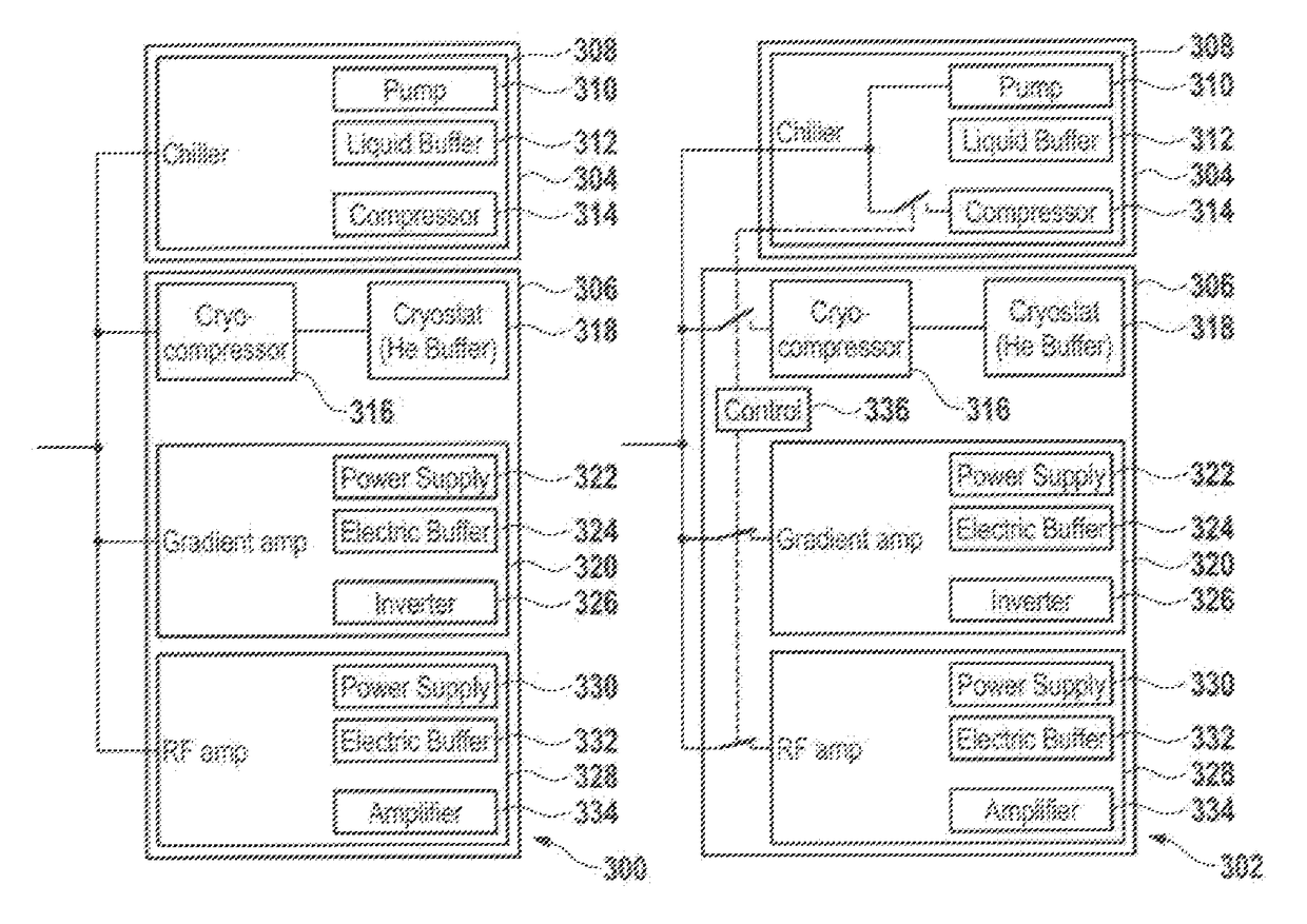
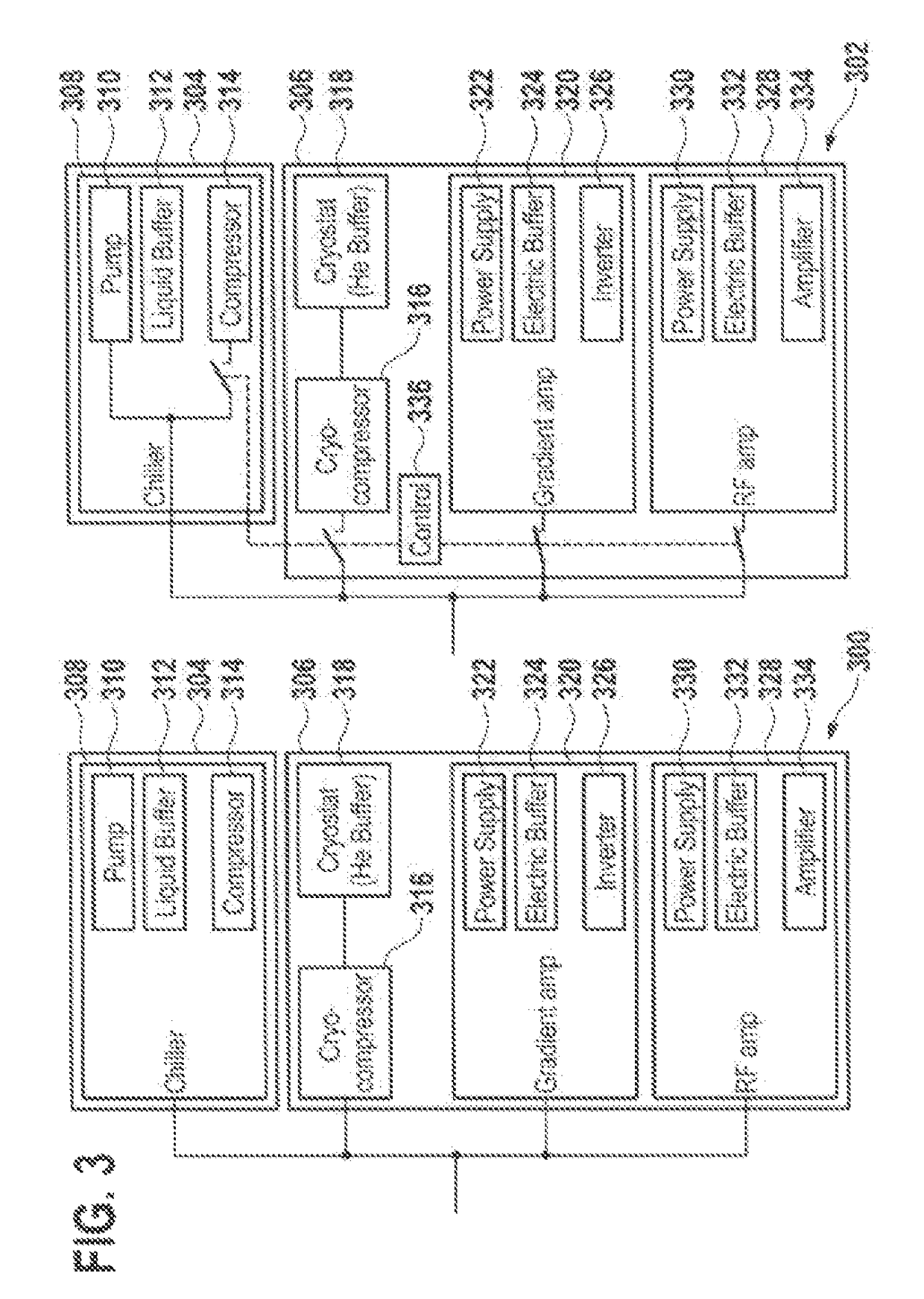
[0051]Like numbered elements in these figures are either equivalent elements or perform the same function. Elements which have been discussed previously will not necessarily be discussed in later figures if the function is equivalent.

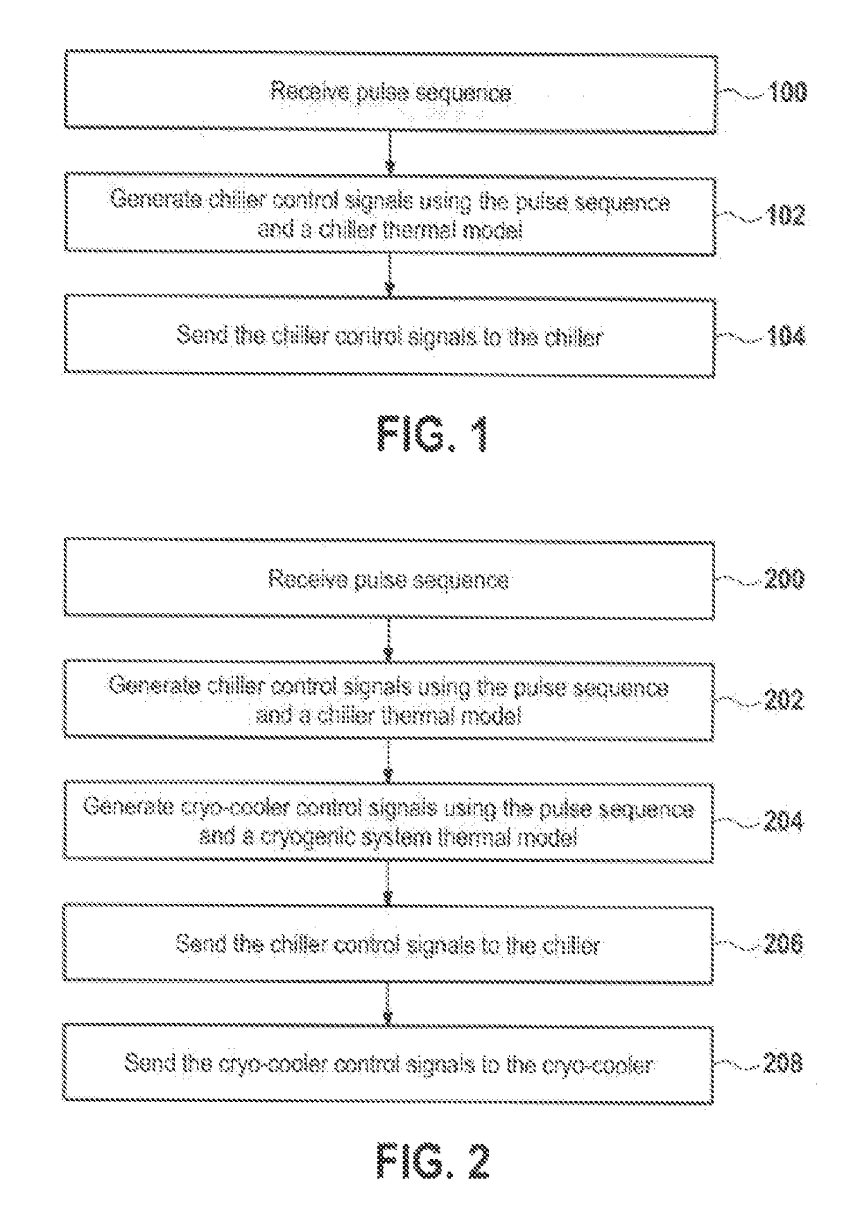
[0052]FIG. 1 shows a flow chart which illustrates a method according to an embodiment of the invention. First in step 100 a pulse sequence is received. Next in step 102 chiller control signals are generated using the pulse sequence and a chiller thermal model. For instance the pulse sequence could be parsed and using the thermal model a plan could be used to decide when the compressor of the chiller should be switched on or off. Finally, in step 104, the chiller control signals are sent to the chiller.

[0053]FIG. 2 shows a flow chart which illustrates a method according to a further embodiment of the invention. In step 200 a pulse sequence is received. Next in step 202 chiller control signals are generated using the pulse sequence and a chiller thermal m...


PUM


Abstract

A magnetic resonance imaging system (402, 500) includes magnetic field gradient coils (516), a gradient coil power supply (320, 424, 518), a processor (540), and a chiller (308, 526) for providing the coolant to the gradient coils. The magnetic resonance imaging system further includes a memory (546) for storing machine executable instructions (580, 582, 584, 586, 588, 590, 592). The instructions cause the processor to receive (100, 200) a pulse sequence (550), to generate (102, 202) the chiller control signals using the pulse sequence and a chiller thermal model (582) of the gradient coils and the coolant reservoir, and to send (104, 206) the chiller control signals to the chiller. The chiller control signals cause the chiller to halt chilling at least a portion of the time when the gradient coil power supply supplies current to the magnetic field gradient coils.

Description

CROSS-REFERENCE TO PRIOR APPLICATIONS[0001]This application is the U.S. National Phase application under 35 U.S.C. §371 of International Application No. PCT / IB2012 / 051392, filed on Mar. 23, 2012, which claims the benefit of European Patent Application No. 11159498.2, filed on Mar. 24, 2011. These applications are hereby incorporated by reference herein.TECHNICAL FIELD[0002]The invention relates to magnetic resonance imaging, in particular to power management in magnetic resonance imaging systems.BACKGROUND OF THE INVENTION[0003]In Magnetic Resonance Imaging (MRI), gradient amplifiers and their associated magnetic field gradient coils are typically used to provide 3-dimensional spatial encoding of atomic spins located in a magnetic field.[0004]These gradient amplifiers are typically characterized by high peak power (several 100 kVA up to 2 MVA for present-day specimens) and high precision of the generated current waveforms. Circuits consisting of series-connected half or full bridges...

Claims


Application Information

Patent Timeline
Patent Type & Authority Patents(United States)
IPC IPC(8): G01V3/00G01R33/34G01R33/385
CPCG01R33/34023G01R33/3856
Inventor VAN HELVOORT, MARINUS JOHANNES ADRIANUS MARIA
Owner KONINKLJIJKE PHILIPS NV
Learn More