
Pressure sensor device for utility network

a technology of pressure sensor and utility network, which is applied in the direction of water mains, complex mathematical operations, service pipe systems, etc., can solve the problems of short life time, high power consumption, and need external power supply, and achieve the effect of compact devices

Active Publication Date: 2017-05-04
KAMSTRUP
View PDF1 Cites 3 Cited by
  • Summary
  • Abstract
  • Description
  • Claims
  • Application Information

AI Technical Summary

Benefits of technology

The patent describes a battery-powered pressure sensor device for monitoring pressure in utility networks, such as water supply systems. The device uses statistical moments to analyze the pattern of pressures and detect pressure transients, which can cause damage to the pipe system and components connected to it. The device can measure and transmit data wirelessly, reducing the amount of data traffic on the network and allowing for battery powering of the device. The device is especially compact, with a single housing that houses all components, including a battery. The technical effects of this invention are improved monitoring of pressure transients in utility networks and reduced power consumption and battery requirements for monitoring devices.

Problems solved by technology

Accordingly, they have high power consumption and require external power supply, or, if battery powered, have a short life time.

Method used


Image

  • Pressure sensor device for utility network
  • Pressure sensor device for utility network
  • Pressure sensor device for utility network

Examples


Embodiment Construction

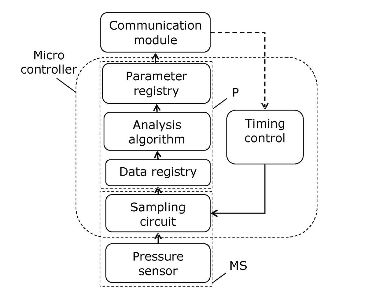
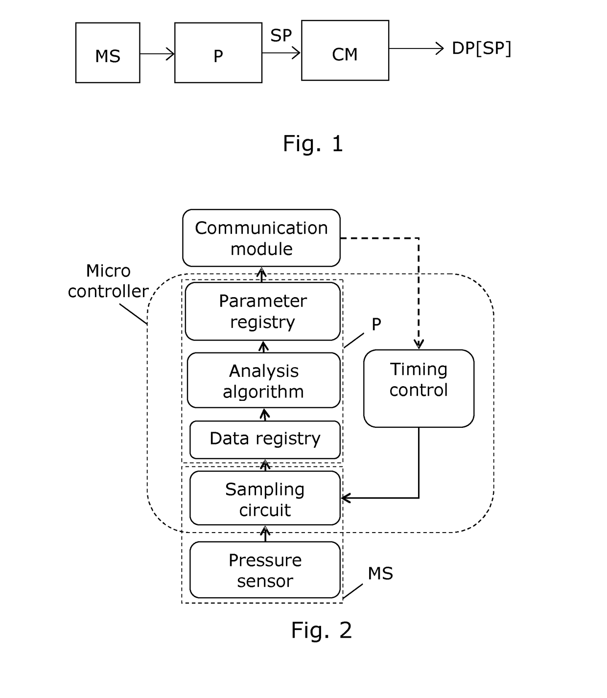
[0064]FIG. 1 illustrates a pressure sensor device embodiment arranged for measuring a pressure in a fluid pipe system, e.g. a utility network. A measurement system MS comprises a pressure sensor and is arranged for performing measurements of pressure at a position in the fluid pipe system, e.g. according to a predefined measurement time sequence. The measurement system MS provides data representing measured pressure values to a data processing unit P.

[0065]The data processing unit P is arranged for processing the measured pressure values or pressure samples, e.g. a predefined number of single pressure values measured within 10-60 seconds, according to a predefined algorithm so as to determine a first statistical parameter SP in response to a plurality of measurements of pressure. E.g. the data processing system is arranged to process the measured pressure values according to a plurality of separate algorithms so as to arrive at the first, and optionally more, statistical parameters ...


PUM

PropertyMeasurementUnit
pressureaaaaaaaaaa
transmission time sequenceaaaaaaaaaa
flow rateaaaaaaaaaa

Abstract

The invention provides a pressure sensor device arranged for measuring a pressure in a fluid pipe system, e.g. a utility network. A measurement system with a pressure sensor serves to measure pressure in the fluid pipe system, and a data processing unit determines at least one statistical parameter in response to a plurality of pressure measurements. Data packets with the statistical parameter is then transmitted by means of a communication module, e.g. via a data network which serves for remote reading of utility meters. The statistical parameter is selected from the second, third and fourth statistical moments of the pressures measured with the plurality of measurements of pressure. The pressure sensor device in a battery driven form can be placed at remote locations in a fluid pipe system to monitor pressure transients, e.g. in a water distribution system. Especially, a time stamp may follow the statistical parameter(s) sent, such that it is possible to track pressure transient creating events on the fluid pipe system.

Description

FIELD OF THE INVENTION[0001]The present invention relates to the field of pressure sensor devices. Especially, the invention provides a pressure sensor device arranged for mounting in a fluid pipe system, e.g. a pipe system forming part of a utility network.BACKGROUND OF THE INVENTION[0002]Pressure sensor devices capable of sensing a pressure in a utility network, such as a water distribution network, are known.[0003]Chinese Patent Application published as CN101308364 A discloses a method of transient analysis in a water distribution network, the method relating to pressure measurements, flow data and data on the network per se to estimate the state of the network.[0004]Also networks of consumption meters with pressure sensors are known.[0005]Japanese Patent Application published as JP3076645 U discloses a system to monitor a water supply line in terms of parameters such as water supply flow, pressure, temperature, chlorine concentration, pH etc., and, upon receipt of data related t...

Claims


Application Information

Patent Timeline
Patent Type & Authority Applications(United States)
IPC IPC(8): G01L19/08E03B7/00G06F17/14G01L19/00
CPCG01L19/086G06F17/14E03B7/003G01L19/0092E03B7/075G01D1/00G01M3/2815
Inventor SKALLEB.AE BUTTED.K, ANDERSSORENSEN, JENS LYKKEROKKJ.AE BUTTED.R, KRISTIAN
Owner KAMSTRUP
Learn More