
Method and device for controlling an inverter

a technology of inverter and control device, which is applied in the direction of electronic commutators, dynamo-electric converter control, dynamo-electric gear control, etc., can solve the problems of inability to avoid overloading some power semiconductor switches, inconvenient operation, and complex technology of inverter, so as to reduce the rotational speed and load the inverter more uniformly

Active Publication Date: 2017-03-28
ROBERT BOSCH GMBH
View PDF14 Cites 1 Cited by
  • Summary
  • Abstract
  • Description
  • Claims
  • Application Information

AI Technical Summary

Benefits of technology

The patent is about a new technology that helps to distribute electrical power more evenly in an inverter. If one part of the inverter is overwhelmed with too much power, the technology can step in and direct more power to another part of the inverter. This can help to keep the entire system running smoothly and efficiently.

Problems solved by technology

Therefore, the power semiconductor switches must be designed for very long switch-on times and for very large currents, generally making the inverter technically complex.
This has the disadvantage that in certain control situations, in particular at very low rotational speeds of the current space vector, some of the power semiconductor switches are permanently thermally loaded, and thus in certain situations, the inverter is loaded non-uniformly, and it is not possible to avoid overloading some of the power semiconductor switches.

Method used


Image

  • Method and device for controlling an inverter
  • Method and device for controlling an inverter
  • Method and device for controlling an inverter

Examples


case 1

[0077] If TATC+delta_T, it is assumed that controllable switches or flyback diodes SDA and SDB have an equal temperature. In this case, a distinction is made between three variants: if GPSGP, delta_I is reduced; and if −GP<=GPS<=+GP, delta_I remains constant. In other words, the deviation angle is increased if overall power dissipation PA+PB decreases as deviation angle delta_I increases. If overall losses PA+PB sincrease as deviation angle delta_I increases, deviation angle delta_I is reduced so that overall losses PA+PB may be reduced, and if change function GPS lies in deviation range delta_GP, deviation angle delta_I remains constant, since the target has already been achieved in this case.

case 2

[0078] If TA<=TB+delta_T and TA<=TC+delta_T, it is assumed that the temperatures of the three controllable switches or flyback diodes SDA, SDB, SDC are equal. In this case, deviation angle delta_I remains constant.

case 3

[0079] If TA>TB+delta_T, it is assumed that temperature TA of the controllable switch or flyback diode SDA is higher than temperatures TB, TC of controllable switches or flyback diodes SDB and SDC. This may be due to load setpoint value m having reached the limit 1 or 0. In this case, a distinction is made between three variants: If GPA+GP, deviation angle delta_I is reduced, and if −GP<=GPA<=+GP, deviation angle delta_I remains constant. In other words, deviation angle delta_I is increased if power PA of controllable switch or flyback diode SDA having the highest temperature decreases as deviation angle delta_I increases, and if power PA increases as deviation angle delta_I increases, deviation angle delta_I is reduced so that power dissipation PA may be reduced. If GPA lies within the limits of deviation range delta_GP, deviation angle delta_I may remain constant, since the target has already been reached in this case.

[0080]With reference to FIG. 6, it is clear that current space ...


PUM


Abstract

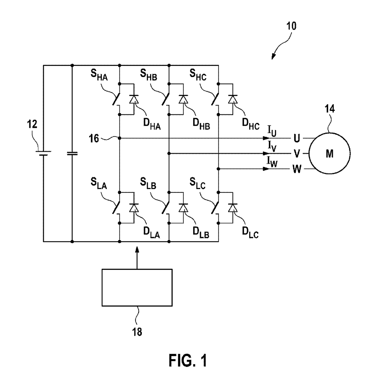
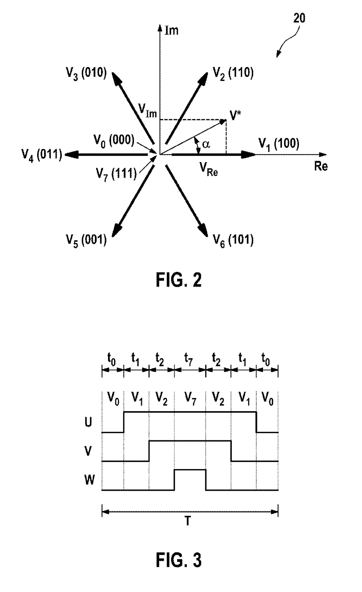
The invention relates to a method (60) for controlling an inverter (10) using space-vector pulse width modulation, in particular to control an electric machine (14), said inverter (10) being equipped with a plurality of controllable switches (S) and being designed to provide a polyphase electric current (IU, IV, IW), in particular to supply multiphase electric current to an electric machine (14). In said method, a reference phase angle (alpha_R) is predefined, and the inverter (10) is controlled in such a way that a plurality of different successive switching states (V0-V7) is established for the switches (S) in order to provide the electric current (IU, IV, IW) in the form of a current space vector (I*). The inverter (10) is controlled in such a way that the current space vector (I*) is provided at a phase angle (alpha_I) which differs from the reference phase angle (alpha_R), a difference (delta_I) of the phase angle (alpha_I) from the reference phase angle (alpha_R) being determined according to a power loss (PA, PB, PC) and / or a temperature (TA, TB, TC) of at least one of the switches (S).

Description

BACKGROUND OF THE INVENTION[0001]The present invention relates to a method for controlling an inverter by means of space vector modulation, in particular for controlling an electric machine, wherein the inverter includes a plurality of controllable switches and is designed to provide a polyphase electric current, in particular in order to supply an electric machine with electric current in a polyphase form, wherein a reference phase angle is predefined, wherein the inverter is controlled in such a way that a plurality of different consecutive switching states of the switches is configured, in order to provide the electric current in the form of a current space vector.[0002]The present invention furthermore relates to a device for controlling an inverter, in particular for controlling an electric machine, wherein the inverter includes a plurality of controllable switches which are connected for providing a polyphase electric current as a function of a reference phase angle, in partic...

Claims


Application Information

Patent Timeline
Patent Type & Authority Patents(United States)
IPC IPC(8): H02P6/14H02P21/06H02M7/48H02M1/32H02M7/5387H02M1/00
CPCH02M7/48H02M1/32H02M7/53875H02P21/06H02M2001/0054H02M2001/327H02M2007/53876Y02B70/1491H02M1/0054H02M1/327H02M7/53876Y02B70/10
Inventor HIRSCH, MICHELESCHUSTER, ULRICHMERKEL, TINODEFLORIO, ANDREA
Owner ROBERT BOSCH GMBH
Learn More