
Synchronizing processing between streams

a technology of synchronizing processing and streams, applied in the direction of selective content distribution, electrical equipment,pictoral communication, etc., can solve the problems of large delay between the user physically changing the viewing angle and the new view actually being rendered by the vr rendering device, and may not always be sufficiently synchronized with the processing of the first stream

Active Publication Date: 2021-08-31
KONINK KPN NV
View PDF7 Cites 1 Cited by
  • Summary
  • Abstract
  • Description
  • Claims
  • Application Information

AI Technical Summary

Benefits of technology

[0011]It would be advantageous to enable a client device to start processing second stream in a synchronized manner with the processing of a first stream.
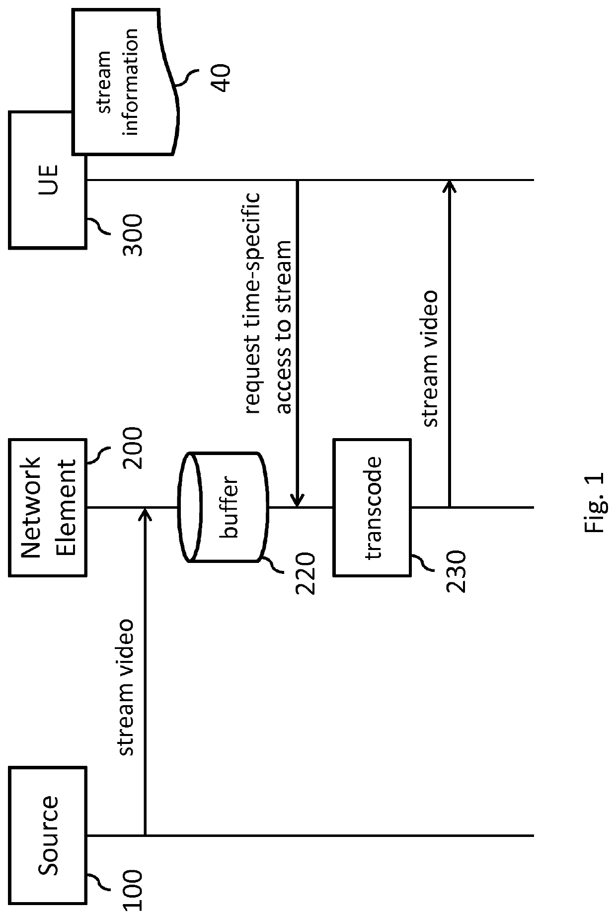
[0029]The above measures may involve facilitating a client device to synchronize streaming and processing a second stream to streaming and processing a first stream. Here, the ‘streaming’ may in the context of the client device refer to the client device receiving the particular stream, e.g., via a network. Moreover, the processing is in the following, by way of example, a play-out of the respective stream. Accordingly, the common content timeline is a common play-out timeline. An example of such synchronized processing may be a switching from streaming and play-out of a first stream to streaming and play-out of a second stream. The above measures may enable such switching to be performed more seamlessly, in that the play-out of the second stream may start at a same or similar point on the play-out timeline as the play-out of the first stream ceases. Here, the term ‘similar’ may refer to the ‘stop’ and ‘start’ points of respectively the first stream and the second stream lying within a neighborhood on the common play-out timeline, or in general refer to the start of the processing of the second stream being synchronized with that of the first stream.
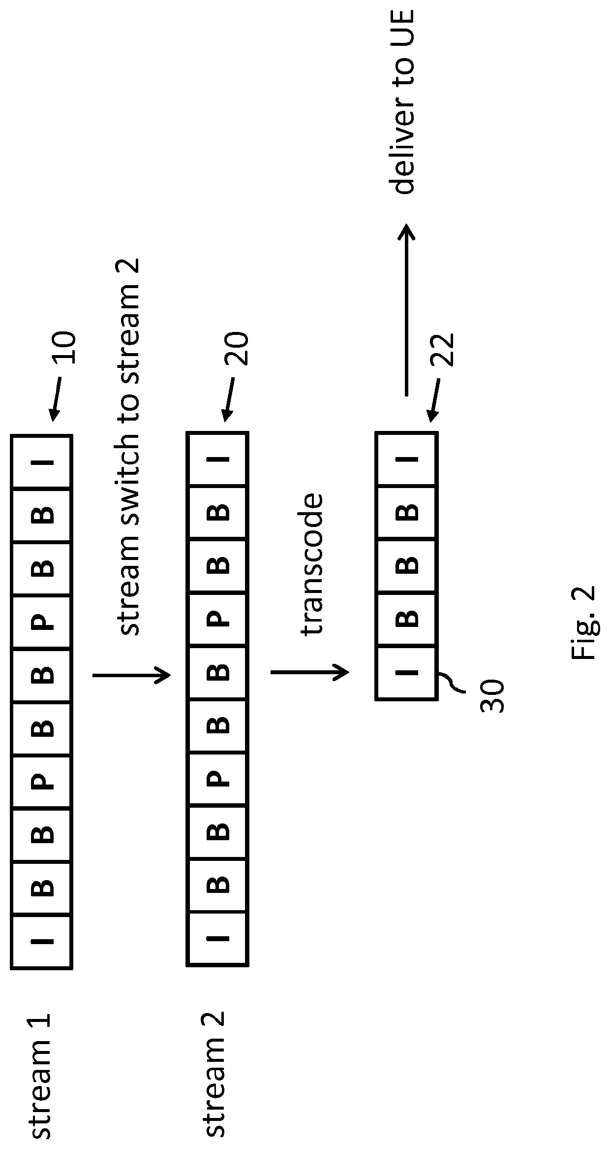
[0034]The above measures may have as effect that a transcoded version of the second stream is generated which may enable the client device to more synchronously start processing the (transcoded version of the) second stream than would be possible when processing the original version of the second stream. Namely, the transcoded version of the second stream may comprise a random access point nearer in time to the selected time point than the original version. As such, the client device is enabled to quicker start playing-out the transcoded version of the second stream. An advantage of the above measures may be that a more seamless switching between streams is provided. Another advantage may be that the client device is provided with direct access to a part, such as a frame, of the second stream. If the transcoding is performed ‘on-demand’ in response to a specific request, the second stream may be specifically transcoded to create a random access point which optimally, or sufficiently well, matches the selected time point indicated by the client device. Effectively, a ‘custom’ version of the second stream may be generated to facilitate the client device to start processing the second stream at a particular moment in time. In addition, although possible, it is not needed for the transcoded second stream to consist of I-frames. Rather, it may suffice for the transcoded second stream to have the above described random access point, e.g., in the form of an I-frame, whereas subsequent frames may again include P-frames of B-frames. As such, the transcoded second stream may be relatively bandwidth efficient. Yet another advantage may be that the streams do not need to be comprised of time-aligned segments to enable start processing or switching at the segment boundaries. Rather, the streams may overlap in time, yet enable start processing or switching at the generated random access point.
[0036]In an embodiment, the method may further comprise receiving an indication from the client device of the selected time point in the form of a byte range or a content timecode in the common content timeline. The client device may explicitly indicate the desired time point in the request, e.g., in the form of the above mentioned byte range or content timecode or in general in any other suitable form. This may have the advantage that the client device is enabled to explicitly indicate at which point in time it desires to start processing the second stream, which enables the random access point to be created in the transcoded second stream to match the desired time point.
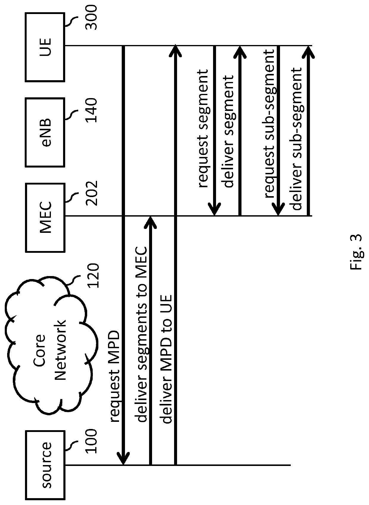
[0063]In general, it may be advantageous to locate the network element nearby a network edge between a core network where a stream source may be located and an access network via which the client device is connected to the core network. Such a location may reduce the distance between the client device and the network element and thereby the latency between requesting and delivering the (transcoded version of the) second stream, whilst refraining from increasing the load on the access network, which would be the case when the network element is located in the access network. It is noted that the network element may nevertheless be located in the access network or further downstream, e.g., in the home gateway, which may still be advantageous, e.g., if a local Wi-Fi connection rather than the access network is a bottleneck.
[0065]In an embodiment, the client device may be configured to switch processing from the transcoded second stream to the second stream at a subsequent random access point in the second stream. The transcoded second stream may be a temporary stream for the purpose of switching to the content of the second stream at a particular time point if such switching is not possible with the original version of the second stream, e.g., by the second stream not having a random access point in the neighborhood (vicinity). Afterwards, the client device may switch to the second stream, e.g., at any of the original random access points in the second stream. An advantage of this embodiment may be that it is not needed to transcode the second stream for a prolonged time, which may be computationally intensive. Rather, the transcoding may be temporary and cease once the client device switches to the second stream.

Problems solved by technology

Disadvantageously, the start of processing of a second stream may not always be sufficiently synchronized with the processing of a first stream.
For example, in VR video, the delay between the user physically changing viewing angle, and the new view actually being rendered by the VR rendering device, may be large.
This delay is henceforth also referred to as ‘switching latency’, and may be sizable due to an aggregate of delays, which includes the delay between requesting a new stream and the new stream actually arriving at the client device.
However, there may be other delays contributing to the switching latency.
For example, when a VR video is rendered on a Head Mounted Display (HMD), there may be a delay in the measurement of a head rotation of a user.
The inventors have recognized that yet another sizeable delay resides in the decoding of the video streams by the client device.
This may result in a client device not being able to decode the first frame which may be received, and rather having to wait until an I-frame is received.
As such, there may be a sizable delay between receiving a stream and being able to start the processing.
A disadvantage of ‘fast channel change’ approaches is that they are unsuitable for enabling a client device to switch between streams from a group of streams which are associated with a common content timeline, or in general to start processing a second stream in a synchronized manner with a first stream.
Namely, ‘fast channel change’ does not enable a switching between time-aligned streams in which the processing, e.g., play-out, of a second stream continues at a same or similar point on the common content timeline as where the processing of a first stream is in time.

Method used


Image

  • Synchronizing processing between streams
  • Synchronizing processing between streams
  • Synchronizing processing between streams

Examples


Embodiment Construction

[0136]The following describes several embodiments of facilitating a client device to synchronize streaming and processing a second stream to streaming and processing a first stream. Here, the client device may also be referred to as ‘user equipment’ (UE), or ‘receiver’, or in VR-related embodiments as a ‘VR device’.

[0137]The streams may be from a group of streams which are associated with a common content timeline. Examples of such streams include, but are not limited to, video streams such as those representing a VR video or a multi-camera recording. However, the streams do not need to be video. Rather, the streams may be of any other stream type which is encoded such that there are dependencies between parts of the stream, with such parts being frames or their equivalent. This includes, for example, means intra-encoded video, sometimes also referred to as intra-frame encoded video. Other examples may be point-cloud or mesh-based encoded scenes, which may also use dependencies betw...


PUM


Abstract

A client device is facilitated to synchronize streaming and processing a second stream to streaming and processing a first stream. Both streams may share a common content timeline. The second stream may be buffered in a data storage. A request for streaming a content part of the second stream may be received. The request may be indicative of a selected time point on the common content timeline from which point onwards the second stream is to be processed. The second stream may then be transcoded to obtain a transcoded second stream. The transcoding may create a random access point in the transcoded second stream from which point onwards the client device is able to decode the transcoded second stream, wherein the random access point is nearer in time to the selected time point than any random access point of the second stream. The transcoded second stream may then be streamed to the client device instead of the non-transcoded second stream, thereby providing the client device with direct access to a part, such as a frame, of said second stream.

Description

[0001]This application is the U.S. National Stage of International Application No. PCT / EP2017 / 083335, filed Dec. 18, 2017, which designates the U.S., published in English and claims priority under 35 U.S.C. § 119 or 365(c) to Europe Application No. 16205213.8, filed Dec. 20, 2016. The entire teachings of the above applications are incorporated herein by reference.FIELD OF THE INVENTION[0002]The invention relates to a method for facilitating a client device to start processing a second stream, which is received by streaming, synchronously with the processing of a first stream, and to a network element configured for the same. The invention further relates to the client device. The invention further relates to a computer program comprising instructions for causing a processor system to perform the method.BACKGROUND ART[0003]Media content such as video content and audio content is commonly delivered to users in a digital form. If media content has a temporal aspect, and in particular i...

Claims


Application Information

Patent Timeline
Patent Type & Authority Patents(United States)
IPC IPC(8): H04N21/43H04N21/2343H04N21/647H04N21/845H04N21/6587H04N21/218H04N21/438
CPCH04N21/4307H04N21/21805H04N21/234336H04N21/234345H04N21/4384H04N21/64784H04N21/6587H04N21/8455H04N21/8456H04N21/43072
Inventor STOKKING, HANS MAARTENNIAMUT, OMAR AZIZ
Owner KONINK KPN NV
Learn More