
Medical staple and magazine

a technology for medical staples and magazines, applied in surgical staples, manufacturing tools, veterinary instruments, etc., can solve the problems of difficult manual control, subtle bending and twisting, and material not necessarily straight, and achieve the effect of smooth feeding of staples

Active Publication Date: 2017-04-04
MATSUTANI SEISAKUSHO CO LTD
View PDF27 Cites 460 Cited by
  • Summary
  • Abstract
  • Description
  • Claims
  • Application Information

AI Technical Summary

Benefits of technology

[0008]Such medical staples in which the legs are relatively shifted can be smoothly used without causing any particular problems if they are loaded in a magazine in which the size of the hanging portions is substantially equal to the length of the legs and the legs become substantially perpendicular to the length direction of the body supporting portion when the medical staples are placed onto the body supporting portion.
[0011]The present invention provides a medical staple realizing smooth feeding when loaded in a magazine and a magazine which can realize stable feeding by using the medical staple.
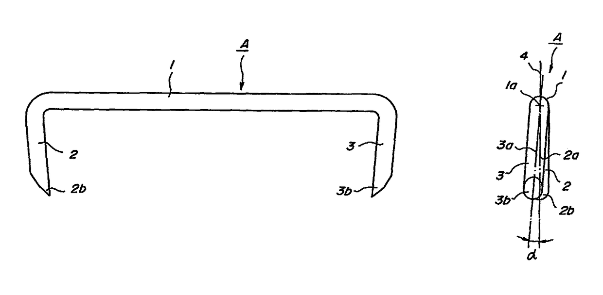
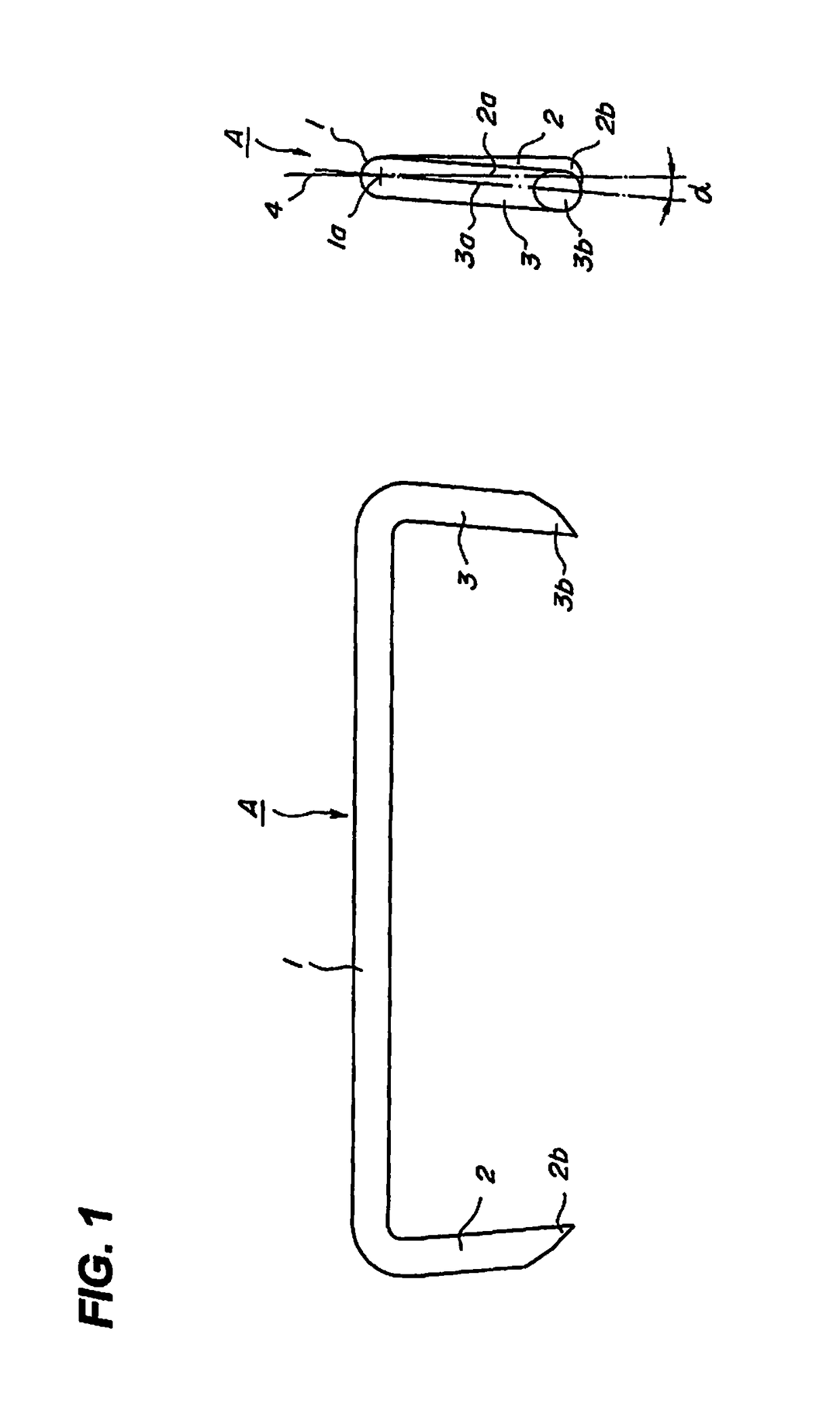
[0016]In the medical staple (hereinafter, simply called the “staple”) according to the present invention, either one of the pair of legs formed at both ends of the body portion is twisted with respect to the plane including the body portion and the other leg in the out-of-plane direction. Thereby, the amount of the shift of the pair of legs can be always a fixed value without being affected by the value of a residual stress varied for each material and the amount of bending or twisting at the time of conveyance. Accordingly, the same amounts of the relative shifts of the pairs of legs of a plurality of staples can be achieved.
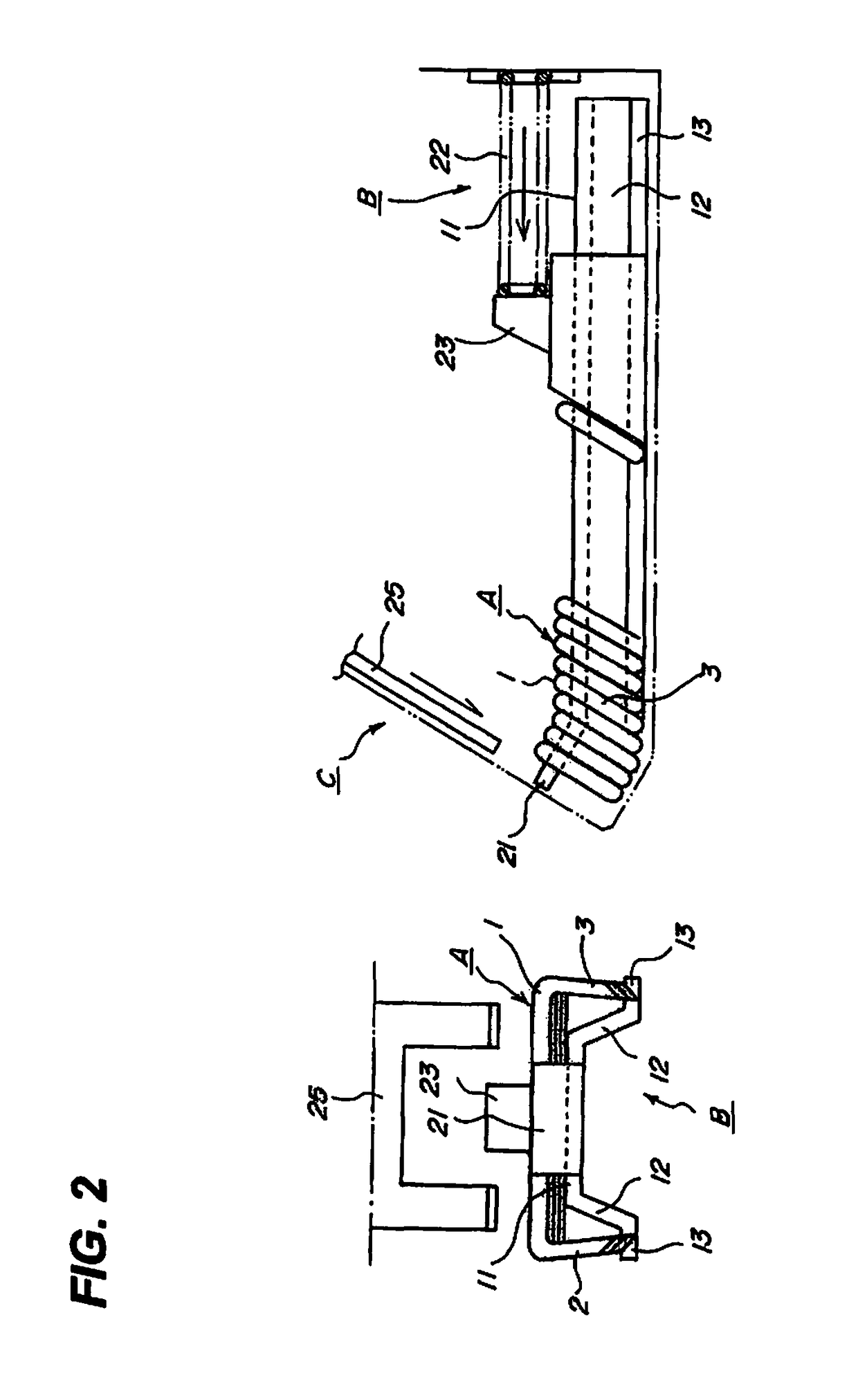
[0017]In the magazine according to the present invention, the staples are loaded in a state where the body portions of the plurality of staples are placed onto the body guiding portion, the tips of the legs are in contact with the leg guiding portions, and the legs are tilted in the downstream direction of the staple moving direction while the body portions are tilted in the upstream direction. Accordingly, the legs of the adjacent staples loaded in the magazine are substantially parallel and are never tangled. As a result, smooth feeding of the staples can be realized.

Problems solved by technology

However, the material is not necessarily straight in the strict sense but subtle bending and twisting can be caused in the material cut to a predetermined length.
Such relative shift of the legs due to the individual nature of the material is caused freely in the progress of each of the processing steps, and is difficult to be controlled manually.
However, if the medical staples are loaded in the magazine in which the length of the hanging portions is shorter than that of the legs of the medical staples and the tip portions of the legs are tilted in the downstream direction of the urging direction of the pusher and the body portions are tilted in the upstream direction of the urging direction when the medical staples are placed onto the body supporting portion, the shifted legs are tangled with the legs of the adjacent medical staple, thereby interfering with smooth movement.

Method used


Image

  • Medical staple and magazine
  • Medical staple and magazine
  • Medical staple and magazine

Examples


Embodiment Construction

[0037]An exemplary embodiment of a medical staple according to the present invention will be described below with reference to the drawing. FIG. 1 is a diagram illustrating the configuration of the medical staple.

[0038]A medical staple A shown in the figure is to suture tissues cut-opened in surgical operations and is formed using a steel wire or a stainless steel wire having a circular cross section. The staple A has a body portion 1 of a predetermined length and a pair of legs 2 and 3 formed by bending the steel wire substantially perpendicularly at both ends of the body portion 1 in a substantially U-shape when viewed from the front side.

[0039]The pair of legs 2 and 3 are formed so as to be tilted to the body portion 1 side so that tips 2b and 3b become closer to each other when the staple A is viewed from the front side. Thus, when the body portion 1 is bent by an anvil 21 of a magazine B to make the U-shaped staple A have a substantially square shape as will be described later,...


PUM

PropertyMeasurementUnit
angleaaaaaaaaaa
twist angleaaaaaaaaaa

Abstract

There are provided a medical staple realizing smooth feeding when loaded in a magazine and a magazine which can realize stable feeding by using the medical staple. Where the medical staple includes a body portion; and a pair of legs formed at both ends of the body portion, wherein the legs are tilted at an angle in which the legs become closer to each other and either one leg is twisted with respect to a plane including the body portion and the other leg in the out-of-plane direction. The magazine includes a body guiding portion which has a size substantially equal to or slightly smaller than the length of the body portions of the staples and carries and guides the body portions thereon; wherein the plurality of staples are loaded in a state where the legs are tilted to the downstream side in the discharge direction and the body portions to the upstream side in the discharge direction.

Description

FIELD OF THE INVENTION[0001]The present invention relates to a medical staple used for suturing biological tissues and a magazine in which a plurality of medical staples is arranged in parallel and loaded in a tilted manner.DESCRIPTION OF THE RELATED ART[0002]In surgical operations, cut-opened affected parts are sutured by medical staples. Such a medical staple includes a body portion and a pair of legs formed at both ends of the body portion, and has a U-shape when viewed from the front side. The tips of the legs are formed as sharp pointed edges so as to reduce piercing resistance at the time of piercing through biological tissues.[0003]The medical staples are manufactured by bending both ends of a straight steel wire having a circular cross section in the direction in which the ends become closer to each other, when the ends have a predetermined angle before they are perpendicular to the center portion of the wire, relatively moving the cutting edge of a punch in the direction th...

Claims


Application Information

Patent Timeline
Patent Type & Authority Patents(United States)
IPC IPC(8): A61B17/068A61B17/064
CPCA61B17/0684A61B17/0644
Inventor KAMEI, TOSHIHARUKATO, KAZUAKI
Owner MATSUTANI SEISAKUSHO CO LTD
Learn More