Welding torch

a welding torch and hose technology, applied in the field of welding torch, can solve the problems of high force, fixed and/or rigid fastening of protective hoses, requiring overcoming resistance, etc., and achieve the effects of reducing the burden on the welder caused by the hose package, reducing the burden on the welder, and improving handling

Active Publication Date: 2017-04-04
FRONIUS INTERNATIONAL GMBH
View PDF19 Cites 1 Cited by
  • Summary
  • Abstract
  • Description
  • Claims
  • Application Information

AI Technical Summary

Benefits of technology

[0010]It is thus the object of the invention to create a welding torch that minimizes the burdens caused by the hose package.
[0012]An advantage of a rotatable and pivotable fastening of the wire core and the protective hose to the torch housing is that the burdens for the welder caused by the hose package are reduced and therefore handling is improved. For example, deviations of the protective hose from the conveying axis are compensated due to the rotatable and pivotable fastening, since a circular movement is possible within a restricted radius. Twisting during the rotating and pivoting movement is prevented as well, in particular regarding the protective hose.
[0013]It is advantageous if the wire core is fastened by a clamping means arranged rotatably within the torch housing, so the wire core may be replaced conveniently.
[0014]A transparent wire inlet nozzle is advantageous as well, allowing a more accurate placing during replacement of the wire core.

Problems solved by technology

A disadvantage here is that this is a fixed and / or rigid fastening of the protective hose.
As a consequence, every movement of the welding torch requires overcoming the resistance of the protective hose and the wire core.
Since the protective hose is designed relatively stable, a correspondingly high force is required, which has a negative impact on the handling of the welding torch.
Together with the weight of the hose package, this required use of force for overcoming the rigidity of the supply lines constitutes an additional burden for the welder.
Another disadvantage for the conveying of the welding wire is present if the wire core is not fixed, so its position may change.

Method used


Image

  • Welding torch
  • Welding torch
  • Welding torch

Examples


Embodiment Construction

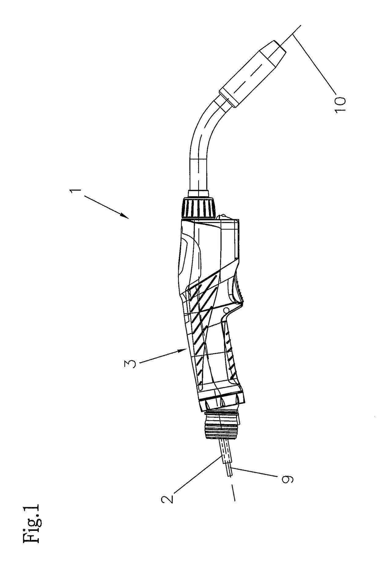
[0018]FIG. 1 shows a welding torch 1 with a pipe bend and a contact nozzle fastened to the torch housing 3. The welding torch 1 is connected to the welding device by a hose package. The protective hose 2, guided into the welding torch 1 by the hose package, is fastened within the handle of the torch, which usually comprises two handle shells. In the protective hose 2, the wire core 9 extends, in which the welding wire 10 is conveyed from the welding device into the welding torch 1 up to the contact tube.

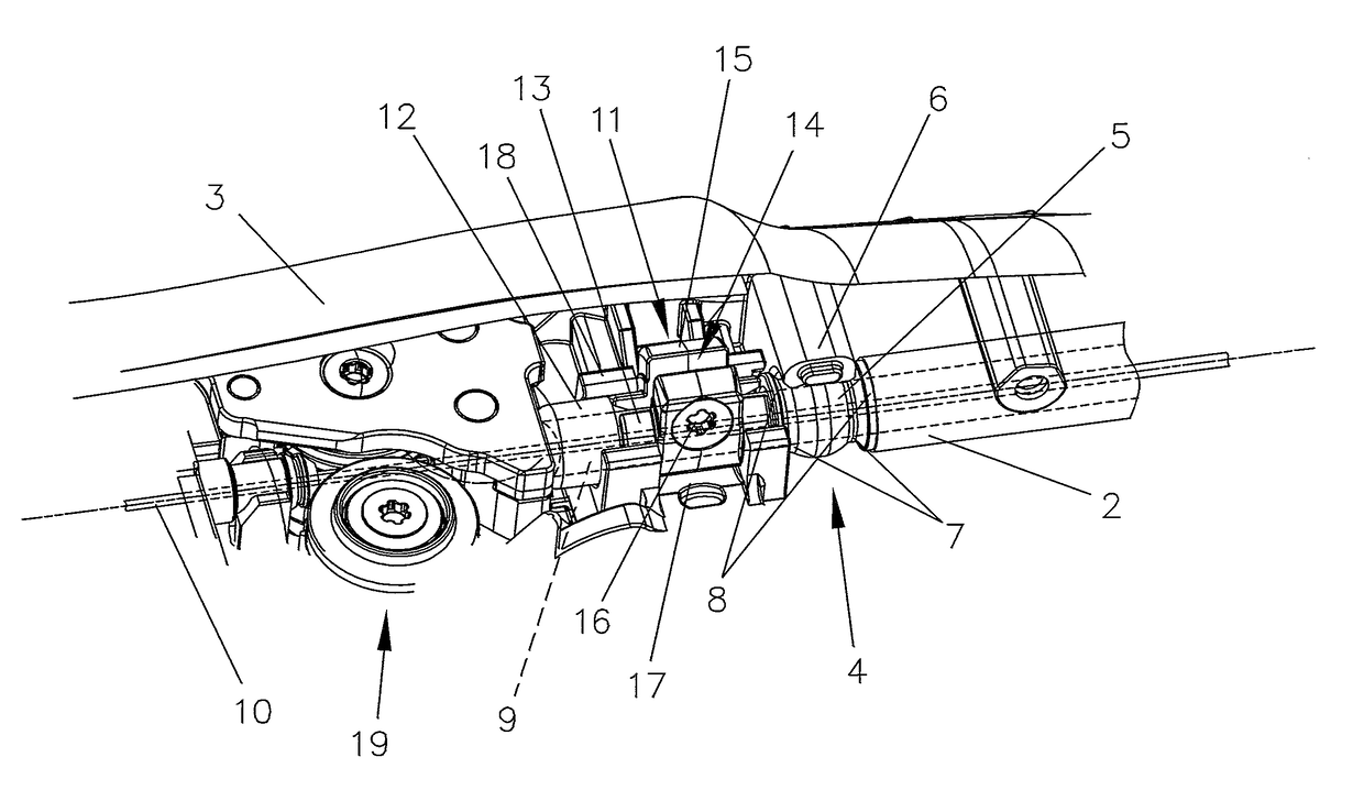
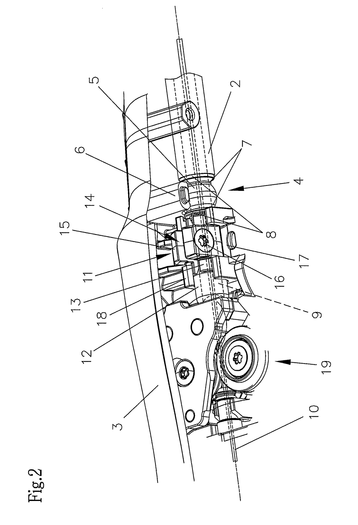
[0019]According to FIG. 2, a metal bushing 4 is arranged form-fit at the end of the protective hose 2. The bushing 4 is basically designed cylindrically, but a central part 5 is sphere-shaped. This central part 5 is used for fastening it within the handle shell, with a rotatable and / or pivotable support being provided and twisting within the torch housing 3 and / or the handle shells being prevented due to the sphere-shaped design. A circular movement of the bushing 4 within a restrict...


PUM

PropertyMeasurementUnit
lengthaaaaaaaaaa
lengthaaaaaaaaaa
transparentaaaaaaaaaa

Abstract

A welding torch, in particular a handheld welding torch, for a melting welding wire, which is guided in a wire core arranged within a protective hose, fastens the protective hose and the welding core within a torch housing of the welding torch independently from one another. For minimizing stresses on the welding torch by the hose package, the protective hose is fastened rotatably and pivotably and the wire core is fastened rotatably to the torch housing.

Description

CROSS REFERENCE TO RELATED APPLICATIONS[0001]Applicant claims priority under 35 U.S.C. §119 of Austrian Application No. A 50577 / 2013 filed Sep. 12, 2013, the disclosure of which is incorporated by reference.BACKGROUND OF THE INVENTION[0002]1. Field of the Invention[0003]The invention relates to a welding torch, in particular a handheld welding torch, for a melting welding wire, which is guided in a wire core arranged within a protective hose, wherein the protective hose and the welding core are fastened within a torch housing of the welding torch independently from one another.[0004]2. Description of the Related Art[0005]A welding torch is usually connected to a welding device by a hose package. The length of the hose package depends on the application and / or the welding torch. When using a push-pull welding torch, the length may be in the range of up to 16 meters. When using a welding torch without a drive unit for the welding wire, the length usually is in the range of 4 meters. T...

Claims


Application Information

Patent Timeline
Patent Type & Authority Patents(United States)
IPC IPC(8): B23K9/28B23K9/10B23K9/12B23K9/133B23K9/29
CPCB23K9/282B23K9/125B23K9/1336B23K9/295B23K9/323
Inventor SORINGAUER, FRANZBRANDSTOTTER, RUDOLF
Owner FRONIUS INTERNATIONAL GMBH
Why Eureka
Try Eureka