Air-conditioning control device for vehicle

a technology for controlling devices and air conditioners, which is applied in the direction of engine starters, process and machine control, instruments, etc., can solve the problems of improper passenger comfort, inability to meet the demand for air conditioning, etc., and achieve the effect of increasing the opportunity

Active Publication Date: 2017-04-04
MAZDA MOTOR CORP
View PDF5 Cites 2 Cited by
  • Summary
  • Abstract
  • Description
  • Claims
  • Application Information

AI Technical Summary

Benefits of technology

[0008]The present invention has been devised in view of the above-described matters, and an object of the present invention is to provide an air-conditioning control device for a vehicle which can increase the opportunity of automatically stopping the engine by the idling stop and also meet the passenger's demand for the air conditioning properly.
[0010]In the present invention, since the idling-stop condition for the roof-open state in which the driver's demand for the air conditioning is relatively low is relaxed so as to make the idling stop to be relatively easily attained, compared to the roof-closed state, the opportunity of automatically stopping the engine by the idling stop is increased, so that the fuel economy can be improved. Further, since the blower fan is driven and thereby the conditioning air is made to blow toward the passenger when the outside-air temperature is the specified temperature or higher or the solar-radiation intensity is the specified degree or greater in the roof-open state in which the driver may be easily influenced by the outside-air temperature or the solar radiation, the air-conditioning system functions as a kind of electric fan, so that the passenger can be prevented from having uncomfortable feelings.
[0011]According to an embodiment of the present invention, the controller of the air-conditioning system is configured to control the air-conditioning system such that at least for a specified period of time after the engine is automatically stopped by the idling stop, the conditioning air from the blower fan flows down through the evaporator and the air-flow amount is adjusted at a first air-flow amount which is smaller than an air-flow amount at the timing right before the engine is automatically stopped by the idling stop. In this embodiment, since the evaporator is sufficiently cooled for a while at the timing right after the engine stop, the conditioning air flowing through the properly-cooled evaporator is made to blow down, so that the passenger can be prevented from having uncomfortable feelings more properly. Further, since the air-flow amount at that time is adjusted so as to be smaller than the air-flow amount at the timing right before the engine is automatically stopped, the cool air can be made to blow down for a properly-long time.
[0014]According to another embodiment of the present invention, the controller of the air-conditioning system is configured to control the air-conditioning system such that an air-flow amount of the conditioning air in a case in which the engine is automatically stopped by the idling stop changes according to at least one of the outside-air temperature and the solar-radiation intensity. In this embodiment, the air-flow amount can be preferably set at a large one for properly preventing the driver from having uncomfortable feelings.

Problems solved by technology

By contrast, if the operation of the air-conditioning device stops, which is caused by the automatic stop of the engine by the idling stop, the passenger may be easily influenced by the outside-air temperature or the solar radiation because the roof is open, so that the passenger may have uncomfortable feelings improperly (the passenger's demand for the air conditioning may not be met).

Method used


Image

  • Air-conditioning control device for vehicle
  • Air-conditioning control device for vehicle
  • Air-conditioning control device for vehicle

Examples


Embodiment Construction

[0027]Hereinafter, a preferred embodiment of the present invention will be described specifically referring to the accompanying drawings.

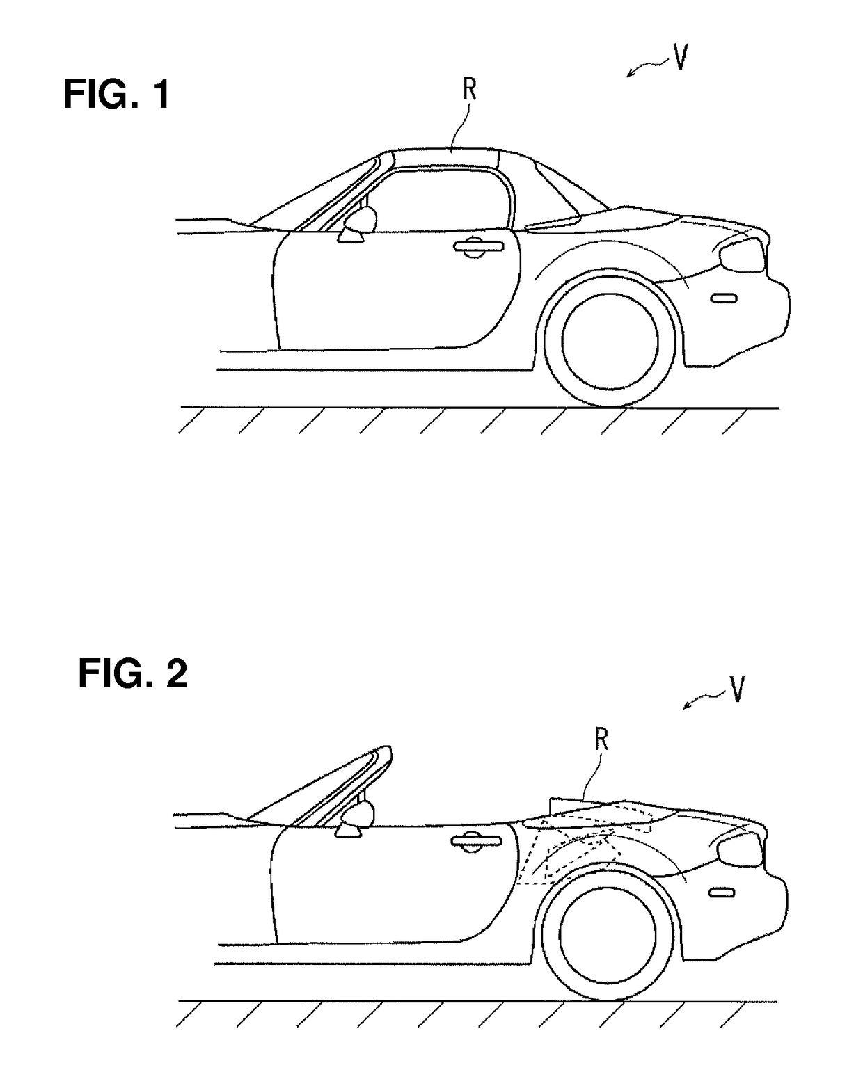
[0028]FIG. 1 shows a vehicle V provided with a roof configured to be open and closed, and a roof-closed state in which a roof R is closed is shown in this figure. FIG. 2 shows a roof-open state in which the roof R is opened from the state of FIG. 1.

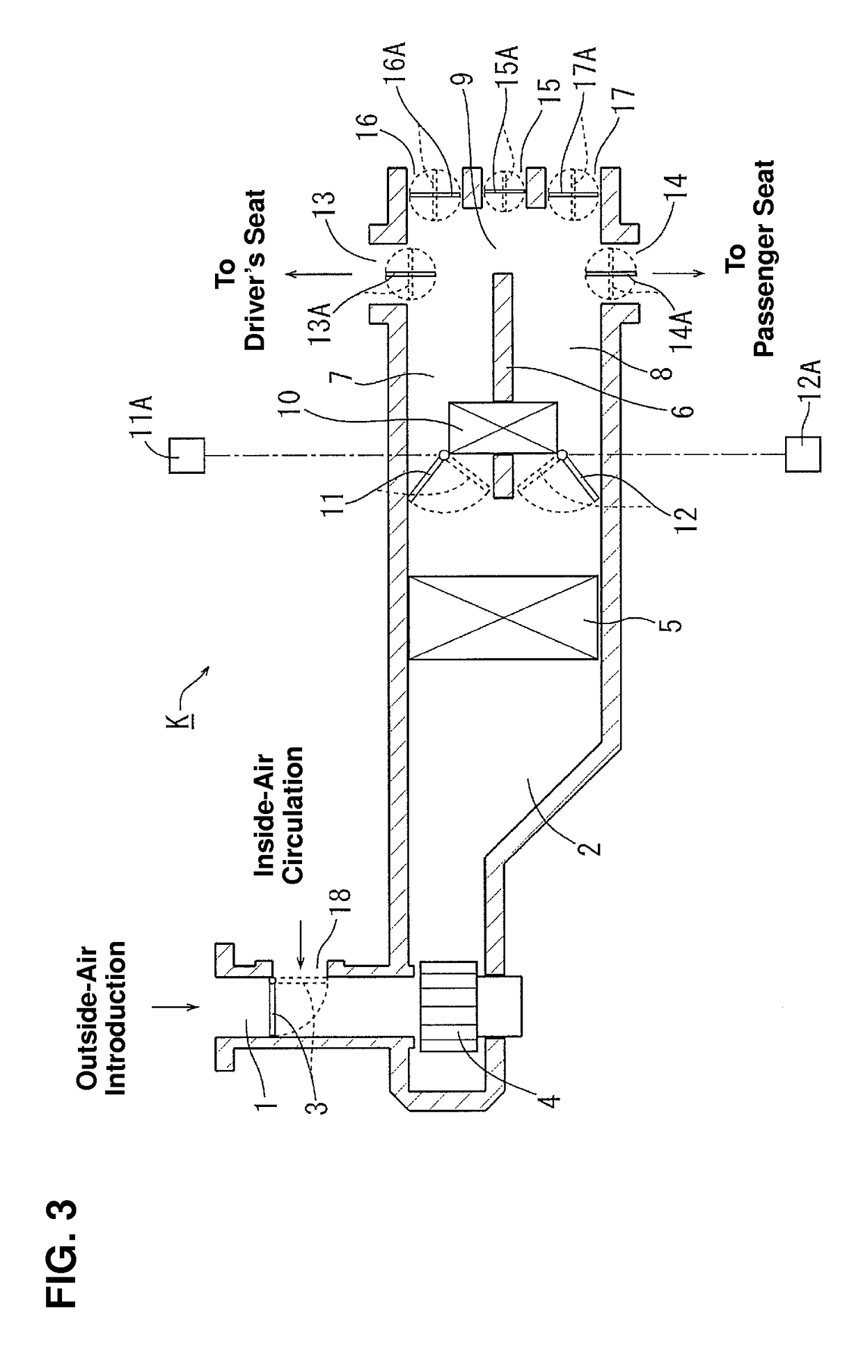
[0029]FIG. 3 shows an example of a passage structure of an air-conditioning system K. The air-conditioning system K is configured such that a switching damper 3, a blower fan 4, and an evaporator 5 are arranged in order from an upstream side (an inlet 1) toward a downstream side in a passage portion 2 including the inlet 1. A portion of the passage portion 2 which is located downstream of the evaporator 5 is divided into two independent passages 7, 8, which are arranged in parallel with a partition wall 6. Respective downstream sides of the independent passages 7, 8 are joined together, and a common cham...


PUM


Abstract

A blower fan is driven, and conditioning air flows down through an evaporator and then is supplied into a vehicle compartment. An idling-stop condition in a roof-open state is set to make an idling stop to be relatively easily attained, compared to a roof-closed state, so that a fuel economy can be improved. When an outside-air temperature is a specified temperature or higher or a solar-radiation intensity is a specified degree or greater at an engine's automatic stop, the blower fan is driven, so that the conditioning air is supplied toward a passenger in a manner of an electric fan. The evaporator through which the conditioning air flows down is sufficiently cool at the timing right after the automatic stop of the engine. Accordingly, it is preferable to configure such that the sufficiently-cooled conditioning air is supplied for a properly-long period of time.

Description

BACKGROUND OF THE INVENTION[0001]The present invention relates to an air-conditioning control device for a vehicle.[0002]In the air-conditioning control device for the vehicle, a cool-air generator including a compressor, a condenser and an evaporator and a hot-air generator with a heat source of engine cooling water are provided, and conditioning air having a specified temperature is obtained by changing the mixture ratio of the cool air and the hot air. This conditioning air is supplied into a vehicle compartment by a blower fan, in which the amount of the supplied conditioning air is adjusted by changing a rotational speed of the blower fan. Generally, the above-described compressor is driven by an engine and a water pump to circulate the cooling water is driven by the engine as well. Accordingly, when the engine stops, the compressor and the water pump are stopped, so that the cool-air generation function and the hot-air generation function stop.[0003]Further, in the air-conditi...

Claims


Application Information

Patent Timeline
Patent Type & Authority Patents(United States)
IPC IPC(8): G05D1/00B60H1/32B60H1/00B60W10/06B60W10/30
CPCB60H1/3208B60H1/00407B60H1/00421B60H1/00735B60H1/00778B60H1/00828B60H1/00892B60H1/322B60W10/06B60W10/30B60W2510/0642B60W2510/30B60W2550/12B60W2710/30F02N11/0837F02N11/084F02N2200/0806F02N2200/12F02N2200/122Y02T10/40B60W2555/20F02N11/00
Inventor TAKATA, NAOKIMIYAGAWA, KAZUHIROKATO, SHINOBUKAJIMOTO, SHINSHI
Owner MAZDA MOTOR CORP
Why Eureka
Try Eureka