
Integrated hazard risk management and mitigation system

a technology of hazard risk management and mitigation system, applied in the field of managing hazard risk, to achieve the effect of reducing the risk of structural loss, wasting energy, and quickly identifying problems

Active Publication Date: 2017-04-04
UNILECTRIC LLC
View PDF7 Cites 49 Cited by
  • Summary
  • Abstract
  • Description
  • Claims
  • Application Information

AI Technical Summary

Benefits of technology

[0007]The electrical system of a structure, whether residential or commercial, is both a direct source of electrical hazards and a common initiator of fires. To reduce the risk of fire and injuries presented by the electrical system of a structure, the preferred embodiments of the present integrated hazard risk management and mitigation system continuously monitor the status of the electrical system of the structure for electrical system anomalies, such as overload conditions, arc faults, and ground faults. In addition, information is also gathered from a second set of sensors monitoring non-electrical system conditions, such as pre-lightning strike conditions, gas accumulations, and water accumulations. From the totality of the collected information, the electrical system is selectively switched-off, either in whole or in part, before the actual hazard event occurs.
[0009]While the major advantage of the present integrated hazard risk management and mitigations system is the reduction in the risk of structural loss or damage and / or personal injury, these systems also provide for peace-of-mind and financial benefits, as well. For example, insurance companies, always concerned with the reduction in hazard risks, may reduce their rates for individuals and businesses implementing such a system in their homes, offices, or other commercial spaces. Utility companies may become less concerned with the waste of energy due to faults in the electrical system and the connected electrical equipment. Home owners will be able to more quickly identify problems with their appliances and heating and air conditioning systems, thereby allowing for early repair and the subsequent financial savings resulting from efficiently operating electrical equipment.

Problems solved by technology

The electrical system of a structure, whether residential or commercial, is both a direct source of electrical hazards and a common initiator of fires.

Method used


Image

  • Integrated hazard risk management and mitigation system
  • Integrated hazard risk management and mitigation system
  • Integrated hazard risk management and mitigation system

Examples


Embodiment Construction

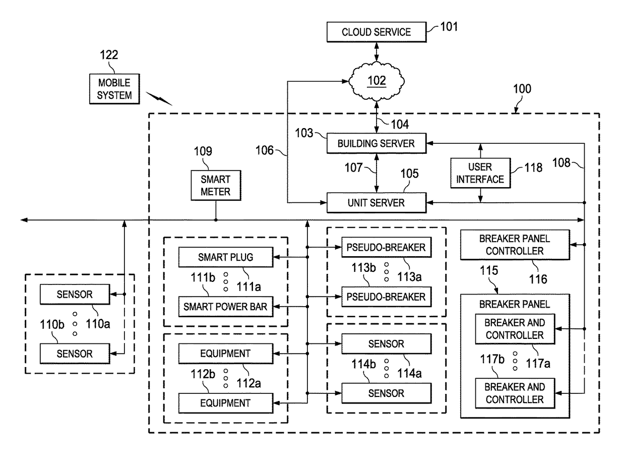
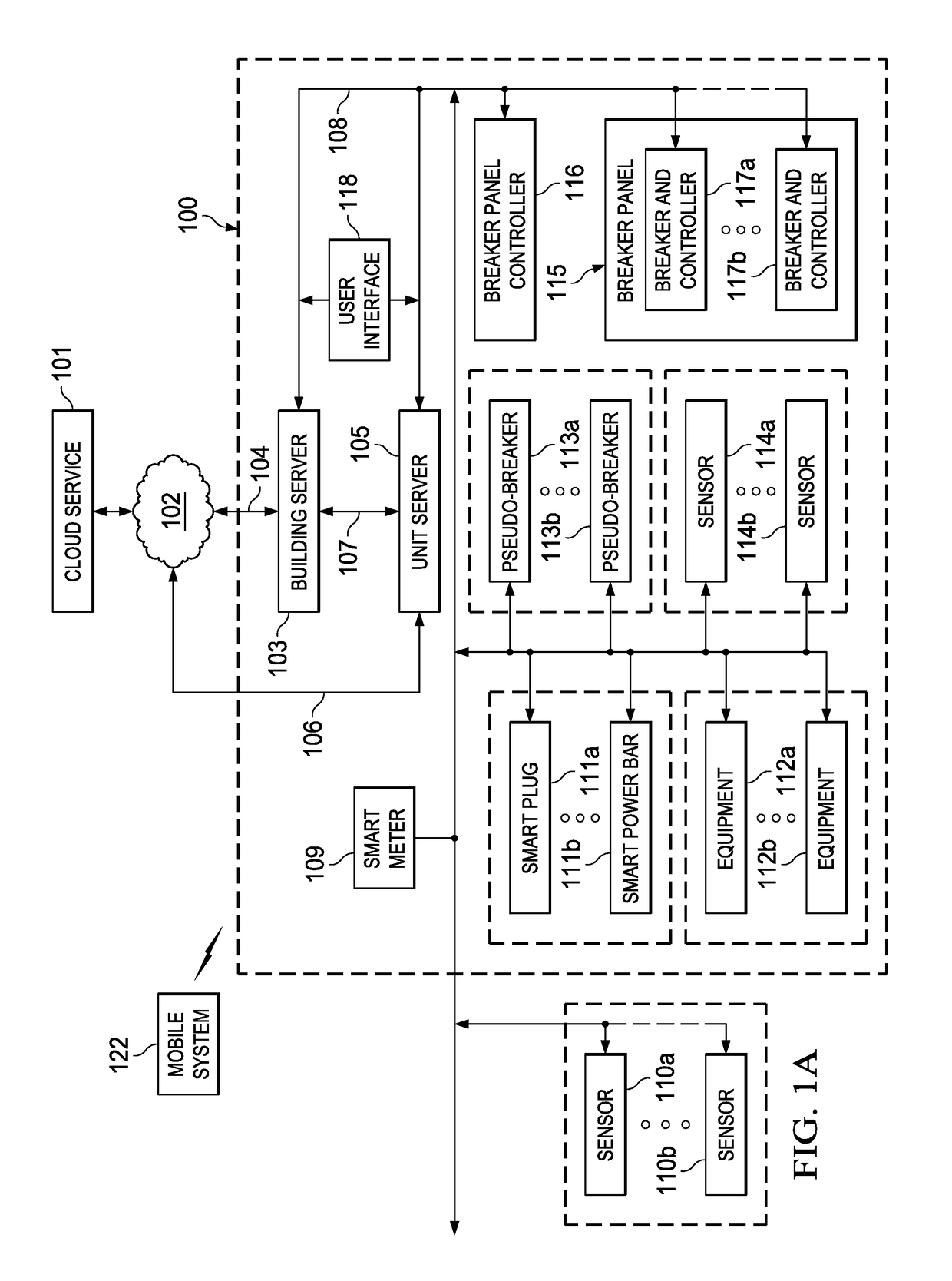
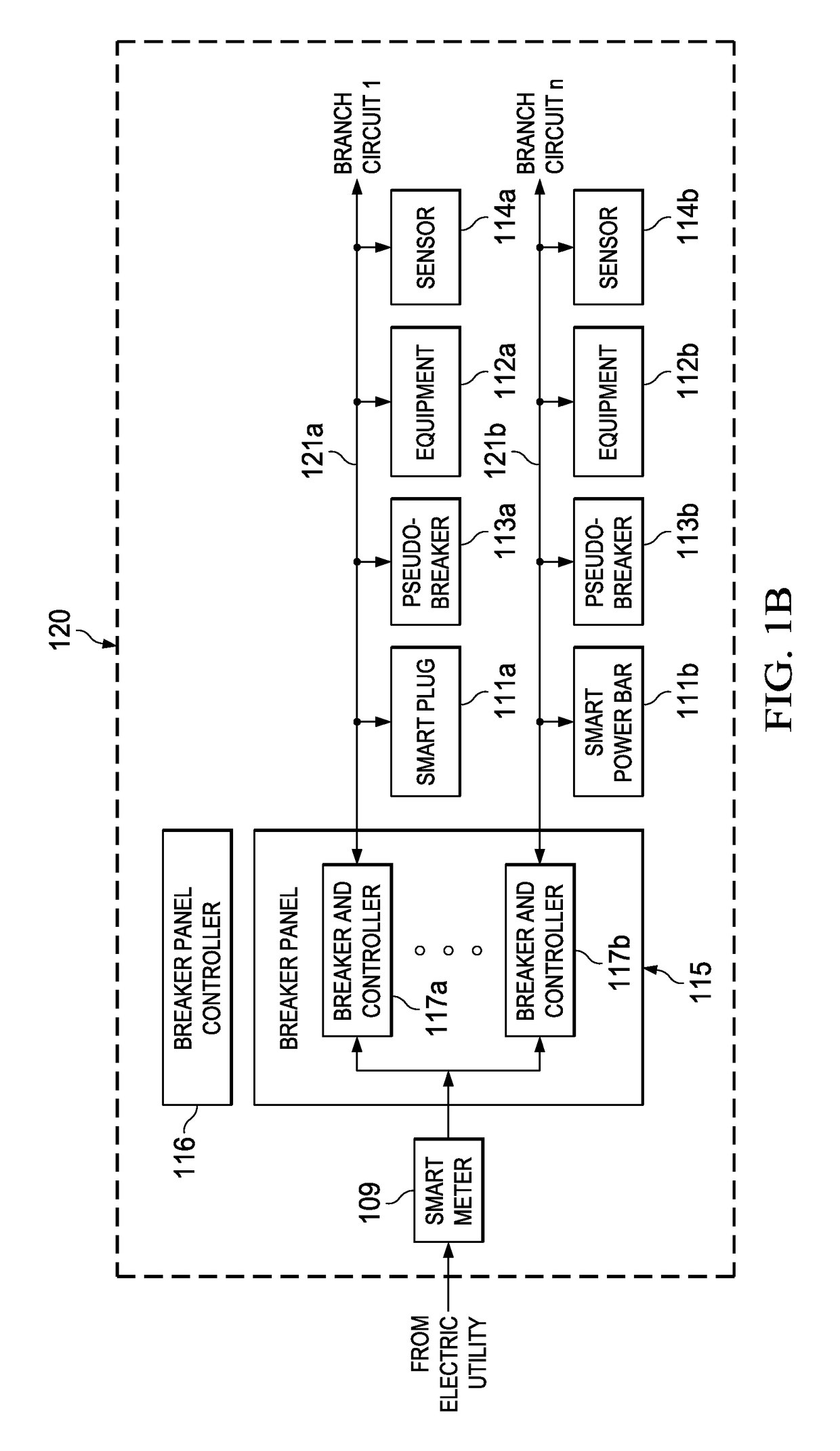
[0025]The principles of the present invention and their advantages are best understood by referring to the illustrated embodiment depicted in FIGS. 1-7 of the drawings, in which like numbers designate like parts.

[0026]FIG. 1A is a block diagram of a networked integrated hazard risk management and mitigation system 100 embodying the principles of the present invention. System 100 is suitable for use in and around any form of building or enclosure that is serviced by electricity and is therefore prone to the risks presented by its electrical system, including the risks of fire and electrocution. For example, structure 100 may be residential housing (e.g., a home, apartment, or condominium), a commercial building (e.g., an office building, large or small retail outlet, or sports and entertainment facility), an industrial building (e.g., a manufacturing facility), or an equipment infrastructure (e.g., as oil platform or other industrial / transportation infrastructure).

[0027]The block dia...


PUM


Abstract

A system for hazard mitigation in a structure including a subsystem coupled to a circuit of an electrical distribution system and set of nodes. The nodes monitor operating conditions of the circuit and generate data in response. A data processing system is operable to process the data generated by the set of nodes and in response identify a trigger representing a condition requiring that an action be taken. The data processing system processes the trigger in accordance with a predetermined policy to initiate an action by the subsystem.

Description

CROSS-REFERENCE TO RELATED APPLICATION[0001]The present application claims the benefit of U.S. Provisional Patent Application Ser. No. 62 / 089,353, filed Dec. 9, 2014, which is incorporated herein by reference for all purposes.FIELD OF INVENTION[0002]The present invention relates in general managing hazard risk related to residential and commercial structures, and in particular to an integrated hazard risk management and mitigation system.BACKGROUND OF INVENTION[0003]The owners and occupants of any structure, including homes, office buildings, and industrial spaces are continuously subjected to the risks presented by hazards, such as fire, flooding, electrical anomalies, and so on. For example, it is well known that fire prevention and control has been a long term problem for civilization. In the past, the prevention of fires spreading was the primary reason for the development of fire brigades. In modern times, most developed countries have also put in place building codes to reduce...

Claims


Application Information

Patent Timeline
Patent Type & Authority Patents(United States)
IPC IPC(8): G08B29/00G05B19/042G06Q10/06G06Q50/06G06Q50/16G08B29/04G05B15/02G05B23/02
CPCG08B29/04G05B15/02G05B19/0428G06Q10/0635G06Q50/06G06Q50/16G05B23/0235
Inventor DAVIDSON, ALISTAIRWEBB, DREW H.
Owner UNILECTRIC LLC
Learn More