Control circuits and methods for active-clamp flyback power converters

a technology of control circuit and flyback power converter, which is applied in the direction of electric variable regulation, process and machine control, instruments, etc., can solve the problem of difficult to optimize the efficiency curve over a wide load range for universal ac input applications

Active Publication Date: 2017-04-04
SEMICON COMPONENTS IND LLC
View PDF5 Cites 9 Cited by
  • Summary
  • Abstract
  • Description
  • Claims
  • Application Information

AI Technical Summary

Benefits of technology

[0006]In an embodiment of control circuit for an active-clamp flyback power converter, the second switch signal control circuit comprises a complementary control signal generator, a non-complementary control signal generator, and a signal controller. The complementary control signal generator generates a first signal according to a first switch signal. The first switch signal is coupled to a transformer of the active-clamp flyback power converter for regulating an output voltage of the active-clamp flyback power converter. The non-complementary control signal generator generates a second signal according to the first switch signal. The signal controller receives the first signal and the second signal and is controlled by the first switch signal and a current sensing signal. The signal controller selectively outputs the first signal or the second signal to serve as a second switch signal according to the first switch signal and the current sensing signal. The second switch signal is coupled for recycling leakage energy of the transformer and achieving a soft-switching of a power switch of the active-clamp flyback power converter.

Problems solved by technology

Since these two control schemes cannot be selectively adopted in one converter, it is difficult to optimize the efficiency curve over a wide load range for universal ac input applications.

Method used


Image

  • Control circuits and methods for active-clamp flyback power converters
  • Control circuits and methods for active-clamp flyback power converters
  • Control circuits and methods for active-clamp flyback power converters

Examples


Embodiment Construction

[0028]The following disclosure provides many different embodiments, or examples, for implementing different features of the invention. Specific examples of components and arrangements are described below to simplify the present disclosure. These are, of course, merely examples and are not intended to be limiting. In addition, the present disclosure may repeat reference numerals and / or letters in the various examples. This repetition is for the purpose of simplicity and clarity and does not in itself dictate a relationship between the various embodiments and / or configurations discussed.

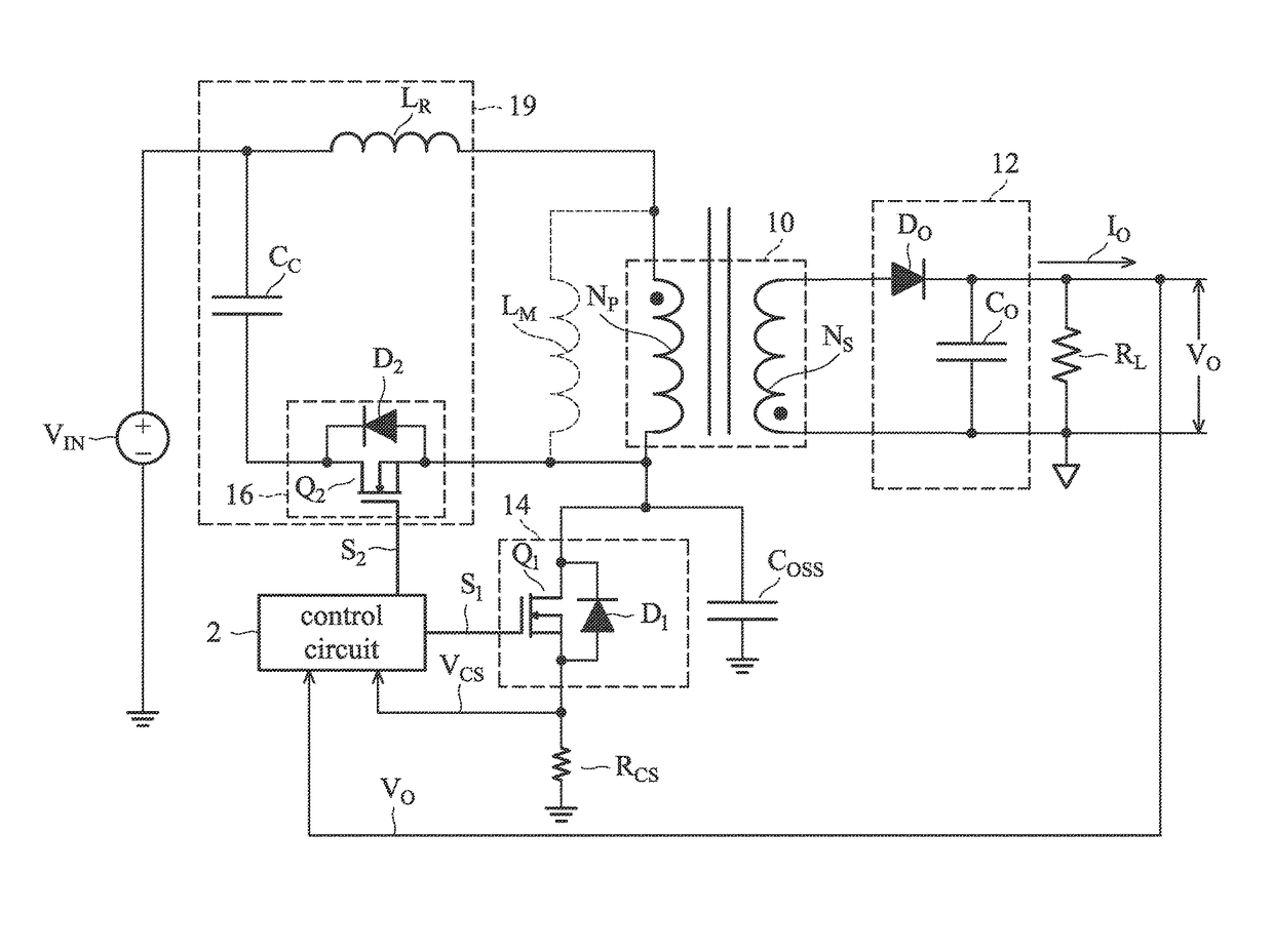
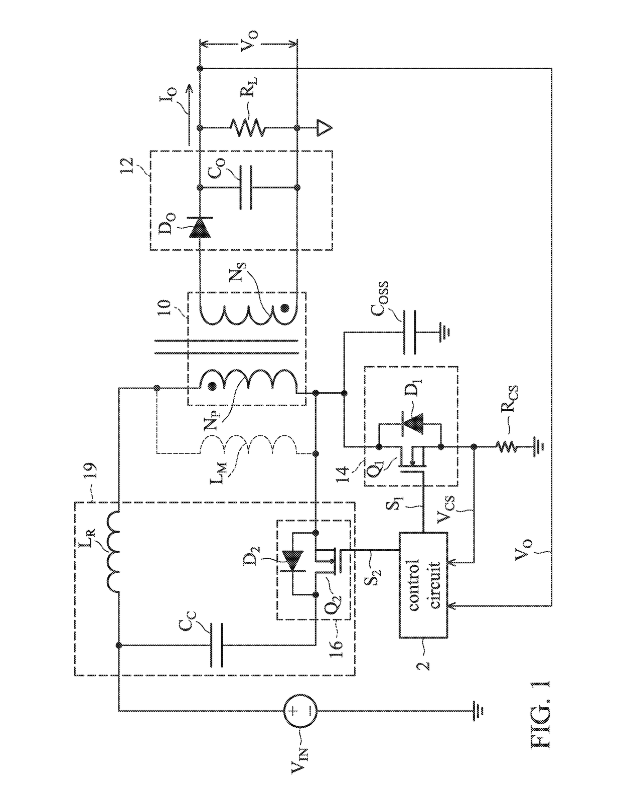
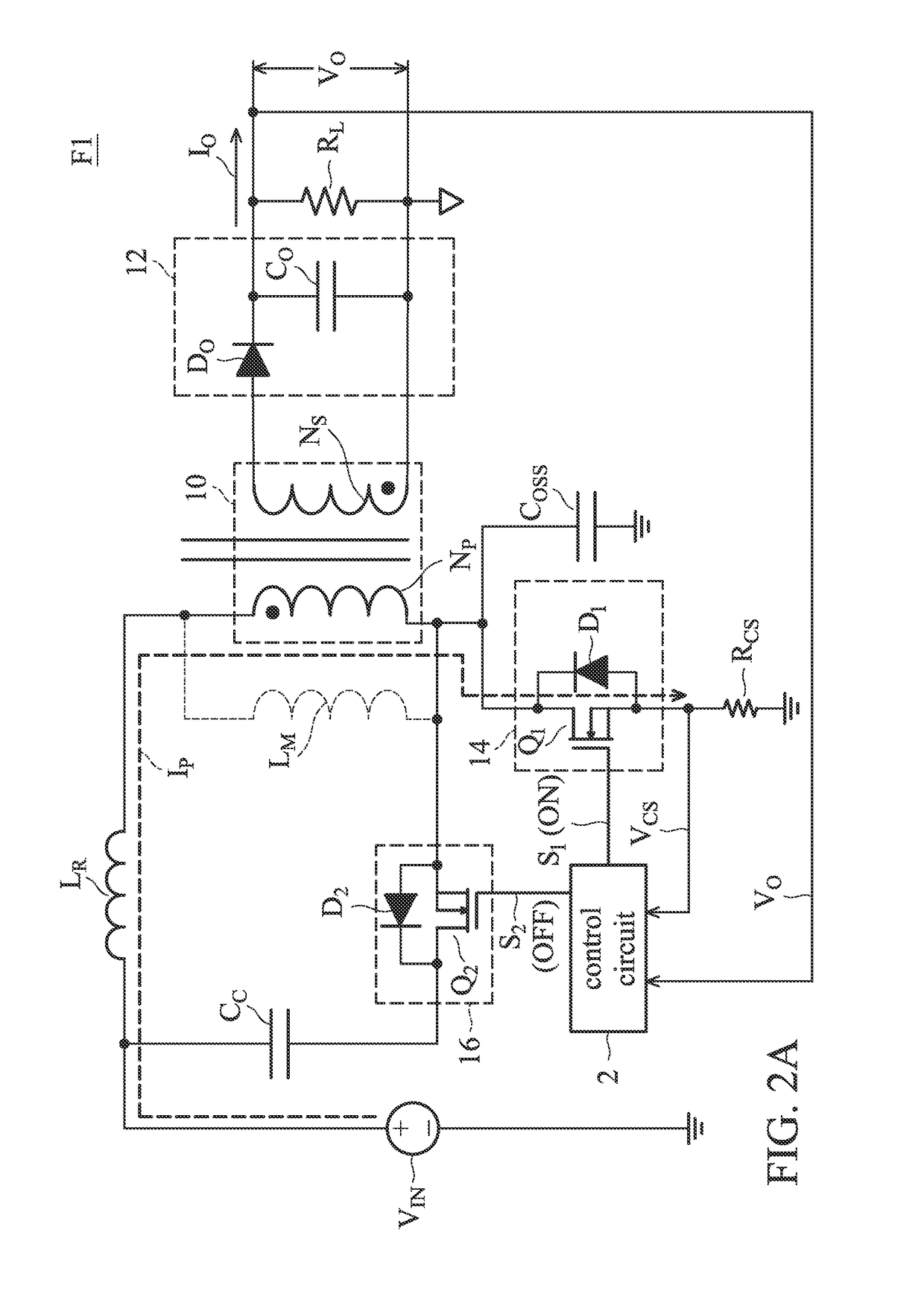
[0029]FIG. 1 is a circuit diagram of an embodiment of an active-clamp flyback converter. The active-clamp flyback converter according to an embodiment comprises a transformer 10, an output circuit 12, a first switch device 14, a second switch device 16, a clamp capacitor CC, a current sense resistor RCS and a control circuit 2. The transformer 10 is coupled to receive an input voltage VIN of the power ...


PUM


Abstract

A method for controlling an active-clamp flyback power converter is provided. The control method comprises: generating a first switch signal according to an output voltage and a current sensing signal, and selectively generating a second switch signal in a complementary or non-complementary control mode according to the current sensing signal and the first switch signal. The first switch signal is coupled to drive a low-side power switch for switching a transformer and the output voltage regulation of the active-clamp flyback power converter. The second switch signal is coupled to drive a high-side power switch for recycling leakage energy of the transformer and achieving a soft-switching of the low-side power switch. With the control method, the high-side power switch can adaptively switch in a complementary or non-complementary control mode depending on the output load and input voltage conditions.

Description

BACKGROUND OF THE INVENTION[0001]Field of the Invention[0002]The disclosure relates generally to power converters, and more particularly it relates to methods and circuits for adaptively controlling active-clamp flyback power converters.[0003]Description of the Related Art[0004]Since the functions of the electronic products are increased, a power supply is needed to provide more output energy. At the same time, consumers demand smaller electronic products, with a smaller volume and lighter weight. These trends form two requirements regarding power converters: raising the power density and improving conversion efficiency. Based on these two requirements, a large amount of active-clamp flyback converters and their derivative circuits are being applied to various power supply products due to their advantages, which include recycling the transformer leakage energy while minimizing turn-off voltage stress and having a soft-switching function for the power switch. For the conventional act...

Claims


Application Information

Patent Timeline
Patent Type & Authority Patents(United States)
IPC IPC(8): H02M3/335
CPCH02M3/33515H02M3/33569Y02B70/10H02M1/0058H02M3/01
Inventor LIU, YEN-MING
Owner SEMICON COMPONENTS IND LLC
Why Eureka
Try Eureka