Device for the acquisition of a stereoscopy image pair

a stereoscopy and image technology, applied in the field of three-dimensional surface reconstruction from stereoscopy image pairs, can solve the problems of specular reflection creating an issue, blocking light, and one would not be able to see through, and achieve the effect of reducing 3d reconstruction artefacts

Active Publication Date: 2017-04-11
QUANTIFICARE
View PDF8 Cites 4 Cited by
  • Summary
  • Abstract
  • Description
  • Claims
  • Application Information

AI Technical Summary

Benefits of technology

[0019]The principle of the present invention is based on the discovery that having two light sources separated by the same distance as the two optics of a double optics, without polarization and aligned with the optics and by using a conveniently designed 3D surface reconstruction algorithm, it is possible to reduce 3D reconstruction artefacts due to specular reflection of the light sources.

Problems solved by technology

Specular reflection is creating an issue for 3D surface reconstruction algorithms as the specular spot observed in each of the two optics is shifted between left and right images of the stereo pair in such a way that the method used to find corresponding points is defining a point which is not within the surface to reconstruct but farther away.
However, if one is holding these two combs in a perpendicular way, then the light is blocked and one would not be able to see through them.
Unfortunately, cross-polarization is removing much of the light and in the example of images of the human skin, they tend to be far from being natural as polarization intensifies the redness of the skin.
All these systems are reducing much of the artefacts due to specular spots but are strongly reducing the light in the images because of light attenuation due to the polarization filters which is far from ideal.
These camera systems are not equipped with computation means enabling 3D surface reconstruction and therefore are not adapted to the use of the dual flash to reduce specular reflection.

Method used


Image

  • Device for the acquisition of a stereoscopy image pair
  • Device for the acquisition of a stereoscopy image pair
  • Device for the acquisition of a stereoscopy image pair

Examples


Embodiment Construction

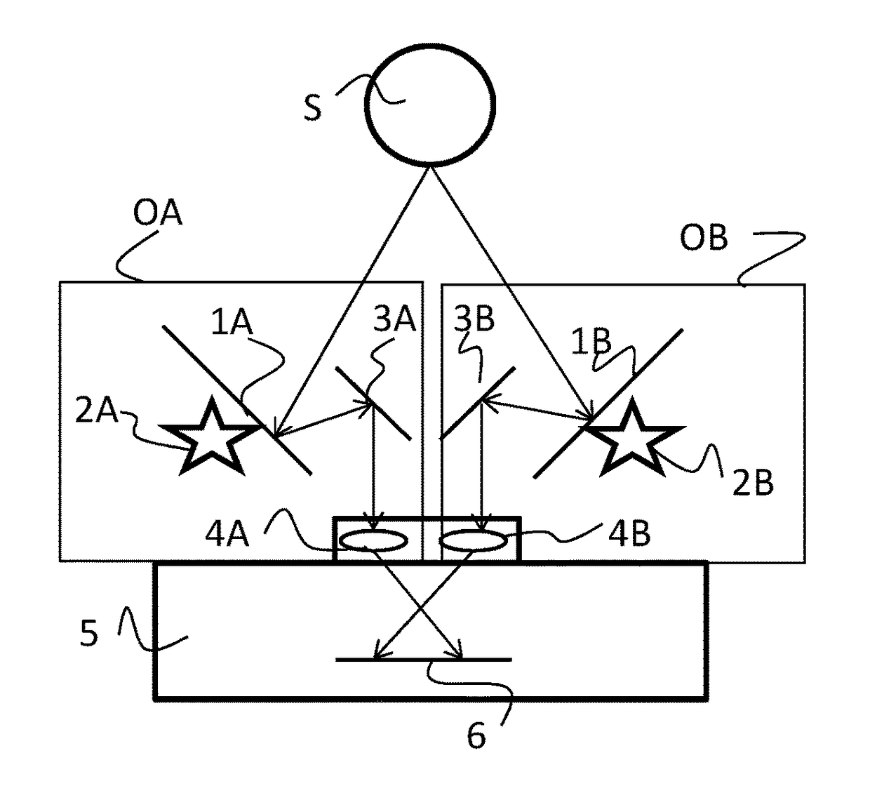
[0037]The present invention is presenting a device intended to improve 3D surface reconstruction algorithms for stereophotogrammetry by reducing the reconstruction artefacts due to specular reflections on the subject.

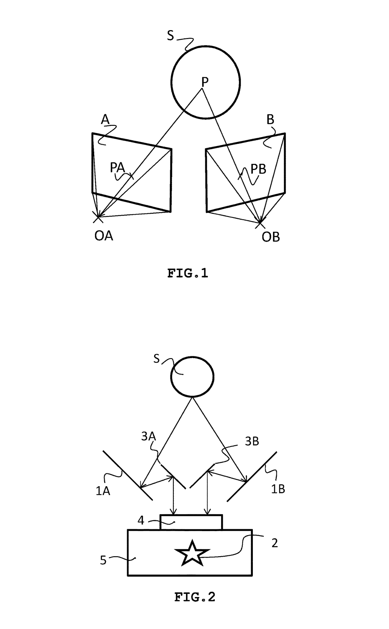
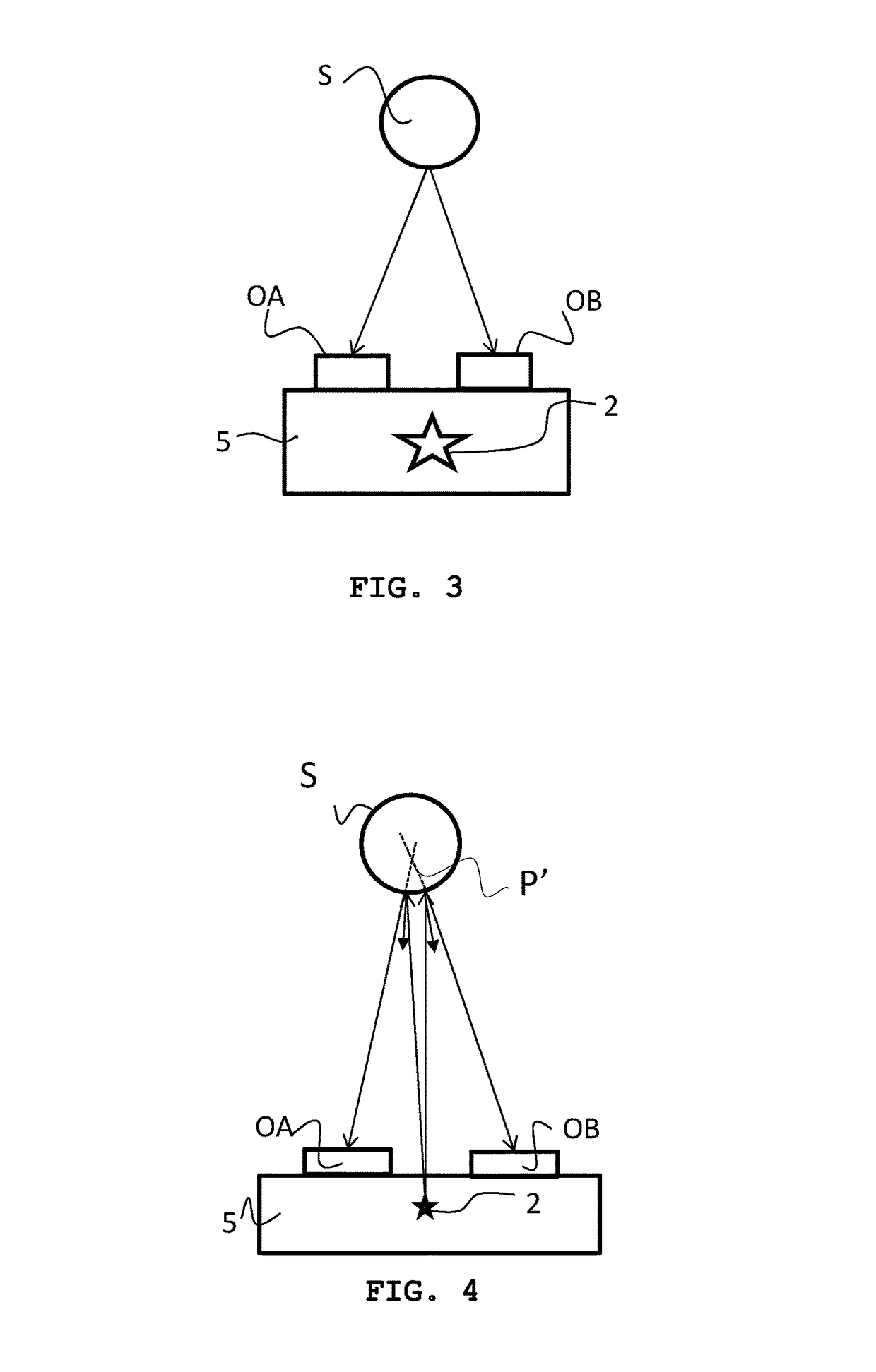
[0038]As an exemplary implementation, it is comprised of a computing unit enabling 3D surface reconstruction by pairing corresponding points between two images of a stereo pair, a photographic camera body with a double optics without polarization and two separated light sources having the same separation distance than the double optics and aligned with the double optics relative to the subject.

[0039]The alignment is such that if the two optics are separated according to a given axis, the alignment between the optical source and the corresponding optics is made according to a line perpendicular to the axis between the two optics. Hence, if the axis between the two optics is horizontal as is the case for human vision, the alignment between each light source and its corres...


PUM


Abstract

A stereophotogrammetry device intended to reduce the 3D surface reconstruction artifacts due to specular reflections when a unique camera body is used. Indeed, specular reflection of the camera flash on shiny objects are creating virtual objects in the scene inducing spikes in reconstruction. The device is constituted of a computing unit (C) enabling 3D reconstruction, a unique camera body (5) equipped with a non-polarized double-optics (OA) and (OB) and two light sources (2A) and (2B) separated by the same distance as the double-optics and aligned with these such that (2A) is aligned with (OA) and (2B) is aligned with (OB) relative to the subject (S). According to geometry considerations, the computing unit (C) is defining the best matching amongst four possible matches relative to the specular spot position.

Description

BACKGROUND INFORMATION[0001]The present invention relates to the field of three dimensional surface reconstruction from a stereoscopy pair of images called stereo pair. Each image of the stereo pair is acquired according to a different viewing angle. The human brain is able to process the stereo pair and mentally reconstruct three dimensions out of it.[0002]Reconstructing a surface in three dimension from a stereo pair is called stereophotogrammetry. Stereophotogrammetry can be based on films or digital images and is extensively being used by cartographers to build topographic maps from aerial images. Through this technology, cartographers are computing level lines enabling the tracing of the relief on maps. Stereophotogrammetry is also used in many applications, including three dimensions reconstruction of industrial objects or skin surface reconstruction for cosmetic or medical applications.[0003]Computers and photography digitizing permitted the development of digital image proce...

Claims


Application Information

Patent Timeline
Patent Type & Authority Patents(United States)
IPC IPC(8): G03B35/00G03B15/02G01C11/02H04N13/00H04N13/02H04N13/239
CPCH04N13/0239G01C11/02G03B15/02G03B35/00H04N13/0025H04N13/0253H04N13/133H04N13/239H04N13/254
Inventor THIRION, JEAN-PHILIPPEPLASSMANN, PETER
Owner QUANTIFICARE
Why Eureka
Try Eureka