Precision attachment system with indirect retainer

a technology of indirect retainer and precision attachment, which is applied in the field of precision attachment, can solve the problems of pain and embarrassment for patients, damage to precision attachments and abutments with supporting bone structure, and difficulty in obtaining a balance of stability and flexibility, and achieve the effect of preventing dislocation and preventing displacement of free-end saddles

Active Publication Date: 2017-04-18
DE BUCK VINCENT
View PDF7 Cites 0 Cited by
  • Summary
  • Abstract
  • Description
  • Claims
  • Application Information

AI Technical Summary

Benefits of technology

[0017]Therefore what is needed is an improved retention bar system than the one described in the aforementioned patent of Helmut Hader CH5957843. This improved retention bar system should prevent the free-end saddles of the dental prosthesis from separating from the mucosa. These problems are overcome by the use of an indirect retainer in combination with a direct retainer: the direct retainer is the C-shaped retention clip and the round section of the retention bar which retains and prevents dislodgement. The indirect retainer is the component that assists the direct retainer in preventing displacement of the free-end saddle away from the mucosa. This is obtained through a lever action on the side opposite the fulcrum line which is located in the centre of the round section.
[0018]The improved retention bar system should thus have a C-shaped retention clip engaging the round bar section, functioning as a direct retainer and a support section with an indirect retainer surface making contact with the dental prosthesis. The support section at the side of the free-end saddles should not make contact with the dental prosthesis when the free-end saddles move in the direction of the compressed mucosa or atrophied alveolar ridge. The ease of replacement of the retention clip via a passage in the dental prosthesis, the guaranteed parallelism of the retention clips and the neutral position of the retention clips during processing should be maintained by means of an adapted spacer clip.
[0019]The support section should guide the round section of the retention bar to the centre of the retention clip to avoid damage to the retention clip during placement of the dental prosthesis. This guidance can be further optimized by the use of a housing of which at least one extremity is closed with a slotted flange guiding the round section of the retention bar towards the centre of the retention clip when the patient places the dental prosthesis in the mouth.SUMMARY OF THE INVENTION
[0023]The retention bar also has a support section between the round section and the underlying mucosa. This support section is off-centred and has at one side sufficient width to provide a passage for the replacement of the retention clip and to make contact between the dental prosthesis and an indirect retainer surface. The indirect retainer surface prevents movement of the free-end saddles of the dental prosthesis away from its tissue support by means of lever action.
[0024]The attachment system is supplied with a spacer clip with two spacer wings of which one spacer wing is extended along the support section opposite the indirect retainer surface. The spacer clip provides ease of processing and guarantees a neutral position and parallelism when multiple retention clips are used. Moreover, it provides a passage for the replacement of the retention clips. The resilience of the free-end saddles in the direction of the compressed mucosa or atrophied bone is not interfered with as the zone underneath the round section of the retention bar opposite the indirect retainer surface is void and will not make contact with the dental prosthesis.

Problems solved by technology

This presents special problems but is necessary to ensure comfort and functionality for the patient.
In particular, when only two abutments are in the jaw which are connected with a retention bar, and the free-end saddles of the dental prosthesis also require support from the alveolar ridge, it is difficult to obtain a balance of stability and flexibility.
If the connection of the dental prosthesis to the retention bar is too rigid, the precision attachments and the abutments with supporting bone structure can be damaged.
This is particularly troublesome and causes discomfort and embarrassment to the patient.
Another frequent problem encountered with the above precision attachment is that the round section does not align with the retention wings of the retention clip when the patient places the dental prosthesis in his mouth.
This causes the retention wings to be bent inwards and destroy the retention clip.
A further drawback is that there is no provision to process the metal retention clip in a neutral position being in contact with the U-shaped surface.
This is of considerable concern when the metal retention clip needs to be replaced in the patient's mouth with autopolymerizing resin.

Method used


Image

  • Precision attachment system with indirect retainer
  • Precision attachment system with indirect retainer
  • Precision attachment system with indirect retainer

Examples


Embodiment Construction

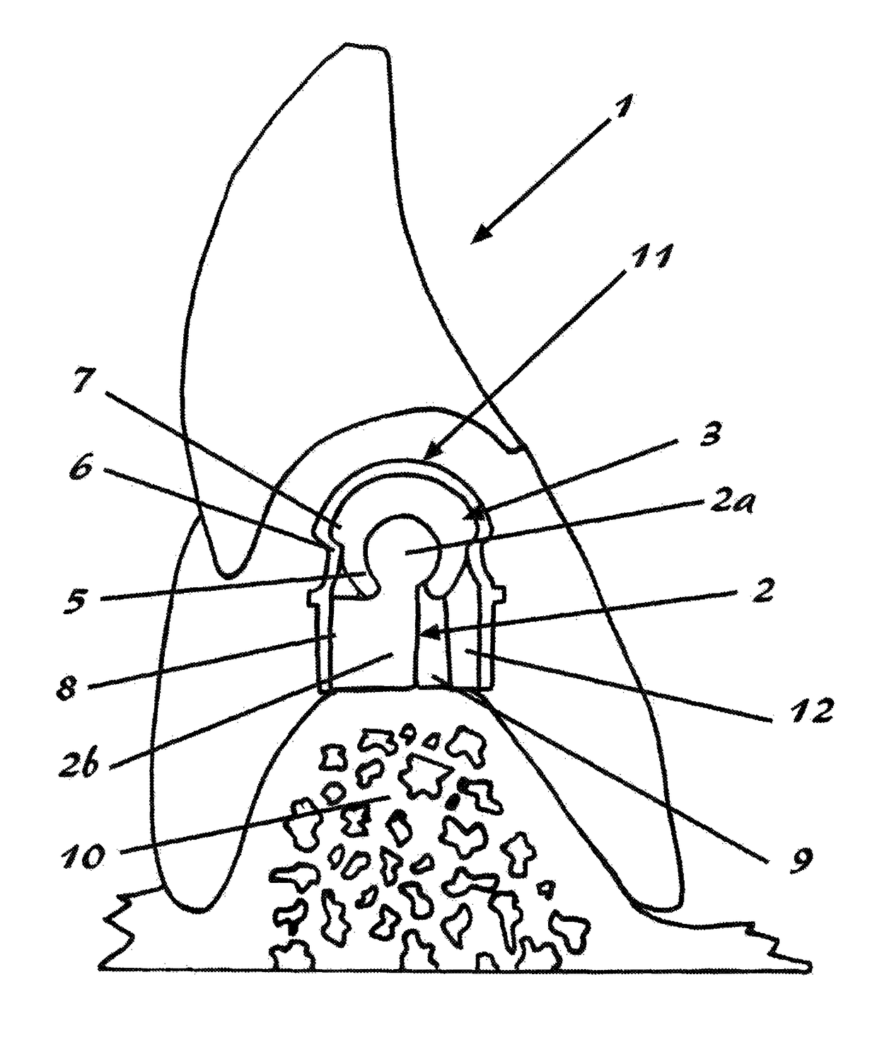
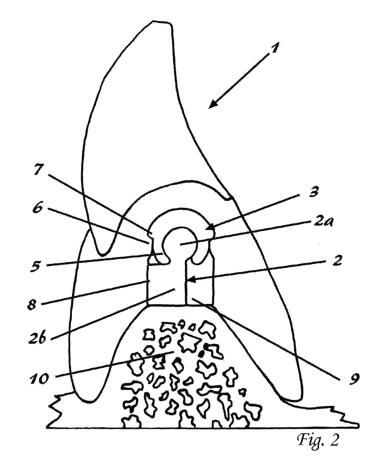
[0048]The retention clip (3) in an elastic material in its preferred embodiment is an open tubular segment having a C-shaped transverse cross section with retention wings (5). The outer aspects of the retention clip (3) have shoulders (7) to engage with the retention ledges (6) in the removable dental prosthesis (1).

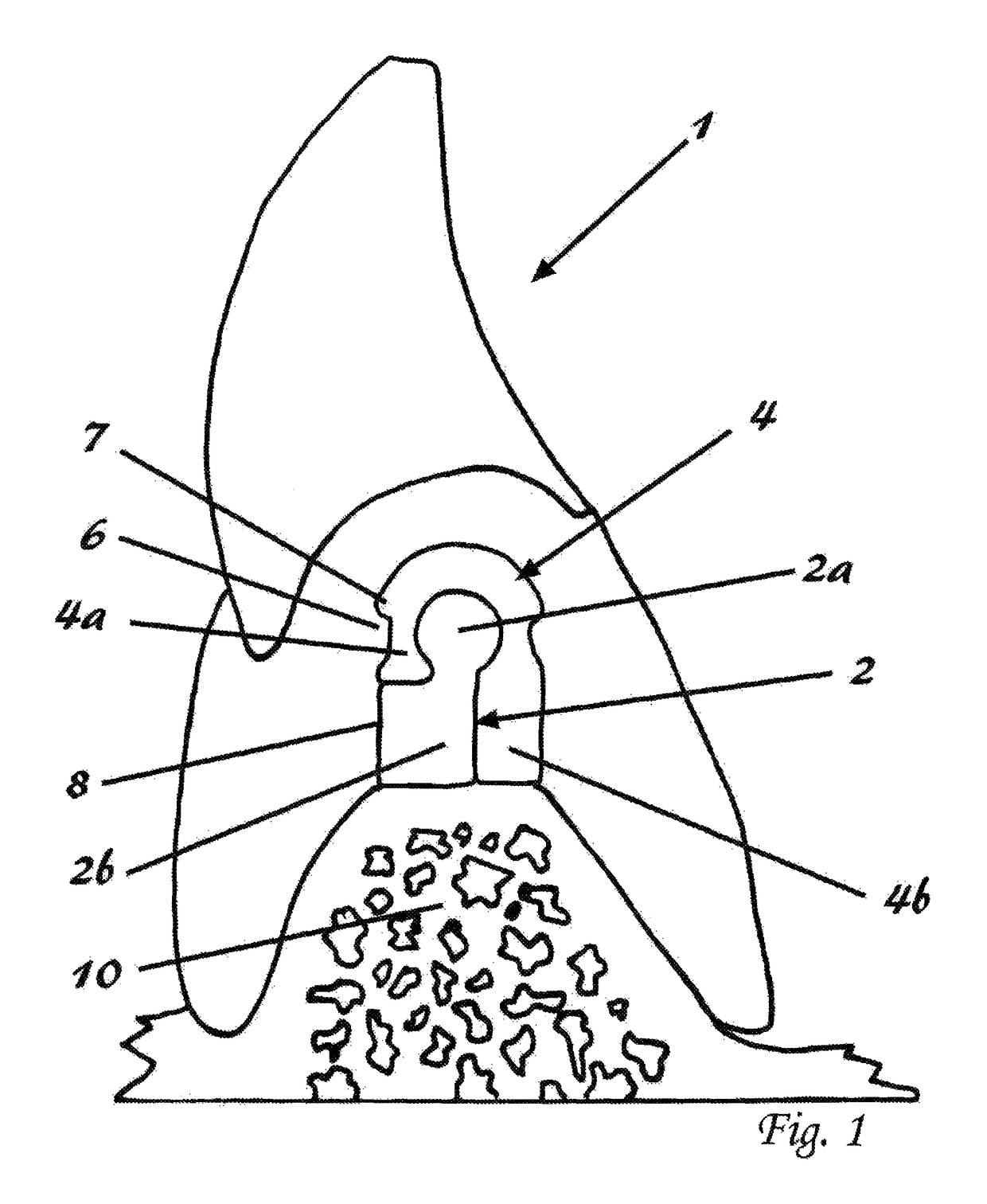
[0049]The retention bar (2) in its preferred embodiment has a round section (2a) which has dimensions to couple with the retention clip (3). The round section (2a) is supported by an off-centred support section (2b). The support section (2b) is on one side sufficiently wide to create a passage (9) for the retention clip (3). The opposing side is less wide and requires an asymmetrical spacer clip (4) which has only one extended spacer wing (4b) to guarantee a passage (9) for the retention clip (3).

[0050]The spacer clip (4) in its preferred embodiment is a tubular plastic segment that has an identical C-shaped transverse dorsal cross section as the retention clip (3). The ...


PUM


Abstract

A precision attachment system for mounting a dental prosthesis to a retention bar having a round section and an off-centered support section, and a C-shaped retention clip which is incorporated into the dental prosthesis and encloses the round section. A spacer clip is adapted for both the retention clip and the retention bar. The contact of the dental prosthesis with the indirect retainer surface of the support section prevents the free-end saddles from lifting off the alveolar ridge. The resilience of the dental prosthesis in the direction of the atrophying alveolar ridge remains possible. The indirect retainer surface and the slotted flange of the housing guide the retention clip to the round section when assembled with the retention bar.

Description

CROSS-REFERENCE TO RELATED APPLICATIONS[0001]This application claims priority to Belgian patent application No. BE 2013 / 0589, filed Sep. 10, 2013, entitled “SYSTÈME D'ATTACHEMENT DE PRÉCISION AVEC RÉTENTION INDIRECTE”, filed by the same inventor and is incorporated in its entirety herein by reference.BACKGROUND OF THE INVENTION[0002]1. Field of the Invention[0003]This invention relates to a device to retain a dental prosthesis in the mouth, commonly known as a precision attachment. More particularly this invention concerns a system for securing a patient-detachable dental prosthesis to a retention bar which is mounted in the mouth, typically with the ends of the retention bar secured in implanted abutments or in crowns on teeth with the retention bar extending along and above the gum line where teeth are missing. A matching C-shaped component is included in the dental prosthesis which connects with the retention bar by means of a snap mechanism.[0004]2. Discussion of Related Art[000...

Claims


Application Information

Patent Timeline
Patent Type & Authority Patents(United States)
IPC IPC(8): A61C13/225A61C13/265A61C8/00A61C13/275A61C5/70
CPCA61C13/2656A61C5/70A61C8/00A61C8/0048A61C13/2255A61C13/275
Inventor DE BUCK, VINCENT
Owner DE BUCK VINCENT
Why Eureka
Try Eureka