
Sensor-based controllable LED lighting system with repositionable components and method

a technology of led lighting and components, applied in the direction of energy saving control techniques, lighting support devices, electric circuit arrangements, etc., can solve the problems of inability of conventional lighting to control lack of advanced control of light sources by conventional lighting, and inability to direct and rotate light panels in selected light fixtures or in selected. , to achieve the effect of reducing the number of conventional luminaires, and increasing the number of lum

Active Publication Date: 2017-04-18
PANOPOULOS PETER J
View PDF22 Cites 51 Cited by
  • Summary
  • Abstract
  • Description
  • Claims
  • Application Information

AI Technical Summary

Benefits of technology

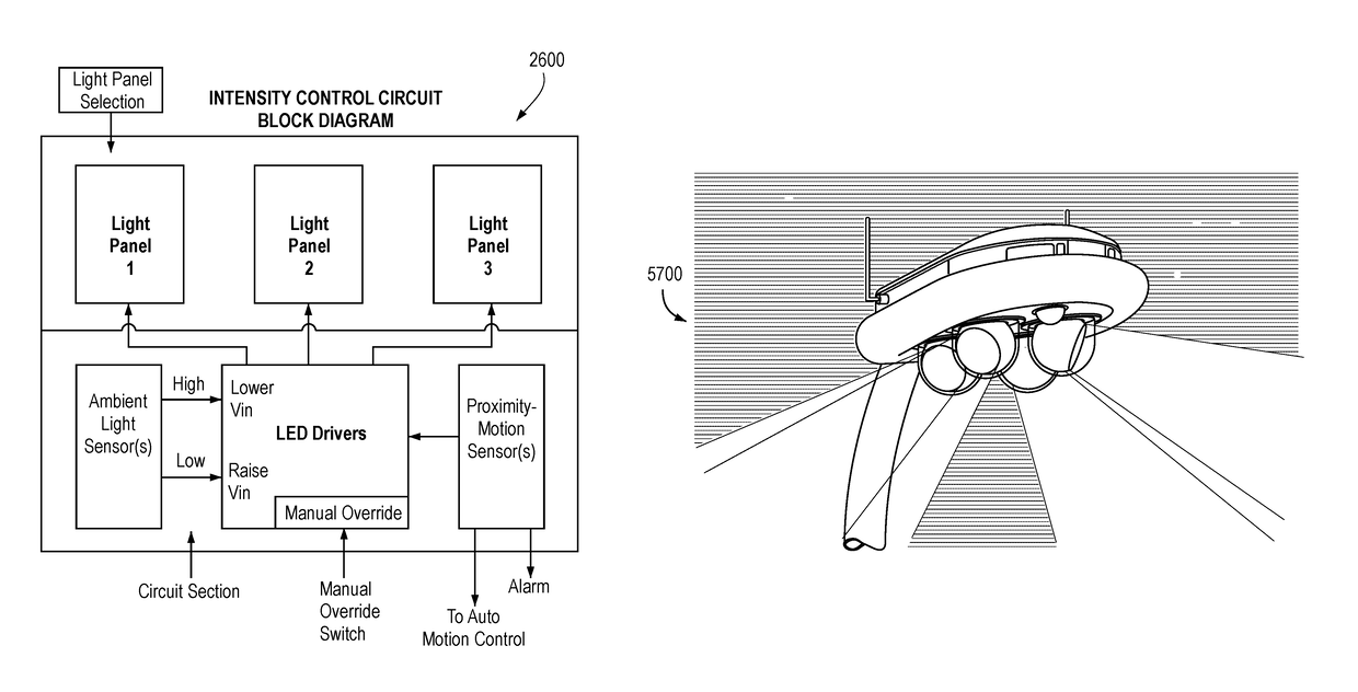
[0023]One or more light intensity sensors may be built into the light fixture to sense a lumen rating of the installed light panel light sources. The sensors may alert users if illumination by a light fixture is less than the rated lumen value and can further determine if the Light Fixture meets default or user-defined brightness levels. Ambient light intensity sensors may determine if dusk or dawn have commenced automatically turn on or off the lighting systems where such ambient light sensors continually monitor surrounding light to turn lights on or off.
[0053]An object of the invention is to reduce replacement costs through component logic, motorized cable lowering features that lower the luminaire from a post, and by using long life Light Emitting Diodes (LEDs) or other long life and energy saving light sources.

Problems solved by technology

However, conventional lighting systems lack advanced control over light sources to direct and rotate light panels to vary the beam angles of the light panels horizontally and vertically, to vary intensity of light panels, and to vary color of lighting panels within a light fixture.
Conventional lighting also lacks an ability to control light panels in selected light fixtures or in selected groups of an array of light fixtures.
Additionally, conventional lighting systems lack a plurality of light panels with servo motors, stepper motors, other motors, solenoids, gears, and / or similar mechanisms to direct light in varying forward and peripheral directions to shine light forward from a light fixture, through the peripheral sides, or to the back of a light fixture.
Similarly, such conventional lighting systems fail to include light panel rotation of between 180 degrees and 360 degrees to allow light panels to shine light forward, through the peripheral sides, or towards the back of a light fixture.
Existing products do not allow a user to save different light intensities, light panel rotation, direction of illumination, monochromatic color for illumination, multicolor light panel illumination configurations, and / or duration of illumination from a light source in memory that can later be scrolled through, recalled and utilized.
Additionally, existing products do not allow a user to rotate light panels to a desired position for illumination, settings relating to such being savable in memory that can later be scrolled through, recalled, and utilized.
Additionally, existing products cannot allow changing color emanating from one or more multicolor light panels within a light fixture, program shining a desired color frequency where and when desired, saving different colors in memory along with a duration for displaying each color, using a timing circuit for when the colors may change, how long each color may be displayed, and to have the ability to step through saved settings and cycles to allow a light fixture or light panel to shine a desired color for a saved time interval.
A problem with conventional lighting systems is that most lighting fixtures are not sufficiently energy efficient due to obsolete light sources.
Existing products lack the intelligent control ability to direct light as might be desired through advanced logic and circuitry making use of stepper motors, servo motors, solenoids, programmable controls, mechanisms and assemblies.
Additionally, existing products lack the ability to intelligently direct the position of lighting panels through default, programmed and / or through user-defined settings.
Moreover, existing products lack the ability to intelligently fine tune lighting direction and intensity through programmed and user-defined settings.
While existing devices may be suitable for the particular purpose to which they address, they are not as suitable for providing stepper motor assisted advanced intelligent lighting systems where light sources are integrated in electromechanically pivotal-rotatable light panels in a fixture to provide light with a wide field of coverage with advanced default, and user defined, selected, and / or programmed directional and intensity settings.
Further, existing devices do not provide sufficiently advanced control over light sources and light fixtures to direct and rotate light panels within one or more light fixtures, vary beam angles of the light panels horizontally and vertically, vary the intensity of light panels, and vary the color of lighting panels with various advanced controllers to create different lighting systems including wired and wireless lighting systems and their respective controls, including computer controlled lighting systems and lighting systems controlled from mobile phones, remotes, or other digital devices for a wide variety of applications.

Method used


Image

  • Sensor-based controllable LED lighting system with repositionable components and method
  • Sensor-based controllable LED lighting system with repositionable components and method
  • Sensor-based controllable LED lighting system with repositionable components and method

Examples


example 3

[0314] Setting the intensity or direction of a group of fixtures in an array. These may be electronically linked by fixture ID numbers. This example will be provided by the paragraphs below. We will select subgroup 3 in a group of five subgroups within an array.

[0315]FCT 6: This selects the MANUAL mode.

[0316]FCT 1 or FCT 2: Selecting the intensity or direction function to control. The DISPLAY may then highlight selections 7-10 and GROUP DISPLAY may prompt with “At which highest level will you start?”

[0317]FCT 7: The user has selected the GROUP level and the GROUP DISPLAY may highlight the five groups (as labeled boxes) from which to select.

[0318]Press 3: Pressing the number 3 may highlight subgroup 3 in the display.

[0319]Once this subgroup is selected, the procedure for setting the intensity or direction proceeds in the same way as in the first two examples. Any command given may be applied to all of the fixtures in that subgroup. This concludes Example 3.

[0320]An example will now b...


PUM


Abstract

A lighting system is provided having a movement system, a light source repositionable via the movement system, a sensor, a controller, and a communication system. The controller may control characteristics of the light emitted by the light source, rotation of the panel by the movement system, and receiving signal information from the sensor. The communication system exchange data between the controller and an external device, the light source and the movement system being remotely controllable by logic received using the controller via the communication system. The light source, the movement system, the controller, the sensor, and the communication system are installable in a drone. Wearable apparatus may be used with the system. Objects may be tracked and illuminated.

Description

CROSS-REFERENCE TO RELATED APPLICATIONS[0001]This application is a nonprovisional application of and claims priority from U.S. provisional patent application Ser. No. 61 / 958,755 filed on Aug. 5, 2013. The foregoing application is incorporated in its entirety herein by reference.FIELD OF THE INVENTION[0002]The invention relates to an LED lighting system. More particularly, the invention relates to an adaptable lighting system with controllable components.BACKGROUND[0003]Lighting systems have been in use for years. Typically, lighting systems include LEDs or other types of light source technologies, such as fluorescent, halogen, high intensity discharge lamps, or sodium vapor. However, conventional lighting systems lack advanced control over light sources to direct and rotate light panels to vary the beam angles of the light panels horizontally and vertically, to vary intensity of light panels, and to vary color of lighting panels within a light fixture. Conventional lighting also lac...

Claims


Application Information

Patent Timeline
Patent Type & Authority Patents(United States)
IPC IPC(8): G05B19/18F21V14/02H05B37/02H05B33/08F21S8/08F21V19/02F21V23/04F21V29/58H05B44/00F21W131/103F21Y105/10F21Y113/00F21Y115/10
CPCH05B37/0209F21S8/085F21V14/02H05B33/0803H05B37/0218H05B37/0227H05B37/0236H05B37/0245F21V19/02F21V23/0442F21V29/59F21W2131/103F21Y2105/10F21Y2113/00F21Y2115/10Y02B20/383Y02B20/46Y02B20/72B64D2203/00G08B13/00B60L53/12H05B47/175H05B47/12H05B47/11H05B47/105H05B47/19Y02T90/16Y02B20/40Y02T10/70Y02T10/7072Y02T90/14B60L2200/10B64U50/37Y02B20/30B64U50/19B64C39/024B64F1/00F21V21/15
Inventor PANOPOULOS, PETER J.RAMSEY, GORDON PAUL
Owner PANOPOULOS PETER J
Learn More