Check patentability & draft patents in minutes with Patsnap Eureka AI!

Method for determining the angular position of an electronic module fixed to the inner face of the tread of a tire

Active Publication Date: 2017-04-25
CONTINENTAL AUTOMOTIVE FRANCE +1
View PDF19 Cites 5 Cited by
  • Summary
  • Abstract
  • Description
  • Claims
  • Application Information

AI Technical Summary

Benefits of technology

The patent describes a method to measure the speed of a vehicle's wheel using an electronic module in contact with the ground. This method is designed to prevent errors caused by the acceleration measurement. It works by calculating a period of revolution for the wheel based on data collected from the electronic module. This calculation is reliable even at high speeds, ensuring accurate measurements. Overall, this technology allows for accurate and reliable speed measurement for vehicle safety purposes.

Problems solved by technology

One of the problems to be resolved by these monitoring systems lies in the requirement for each signal received by the receiver of the central unit to be associated with a data element relating to the location of the electronic module, and consequently the location of the wheel from which this signal originated, this requirement continuing throughout the life of the vehicle; that is to say, it must be met even after wheel changes or, more simply, after reversals of the wheel positions.
At present, however, these location methods are restricted to electronic modules mounted on the rims of vehicle wheels.
On the other hand, the measurement environment is completely different when the electronic module is fixed to the inner face of the tread of a tire: on each revolution, this electronic module comes into contact with the ground and is therefore subjected to an impact which causes the invalidation of the strategy for determining the angular position of said electronic module.

Method used


Image

  • Method for determining the angular position of an electronic module fixed to the inner face of the tread of a tire
  • Method for determining the angular position of an electronic module fixed to the inner face of the tread of a tire
  • Method for determining the angular position of an electronic module fixed to the inner face of the tread of a tire

Examples


Embodiment Construction

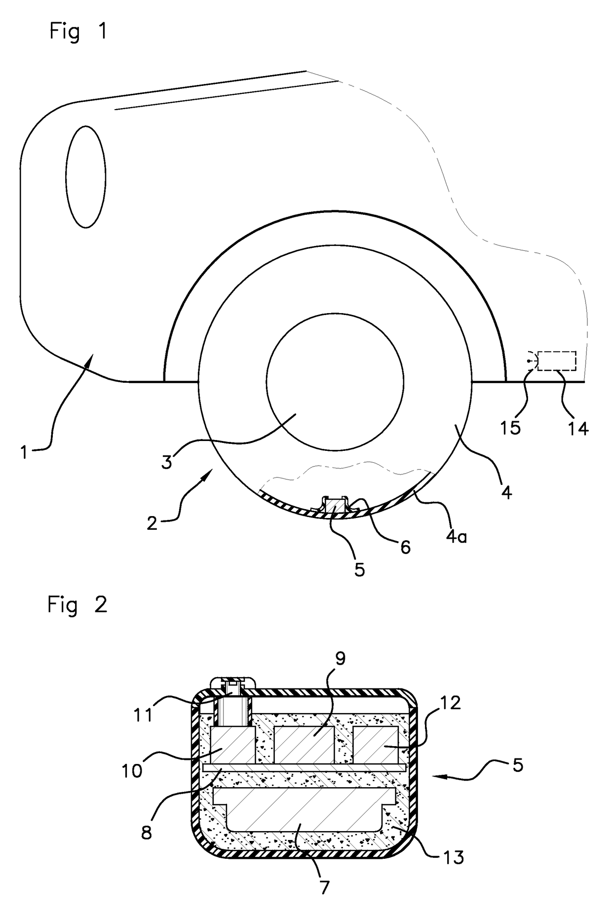
[0032]The invention described below with reference to the attached drawings proposes a method for determining the angular position of an electronic module fixed to the inner face of the tire tread of a vehicle wheel.

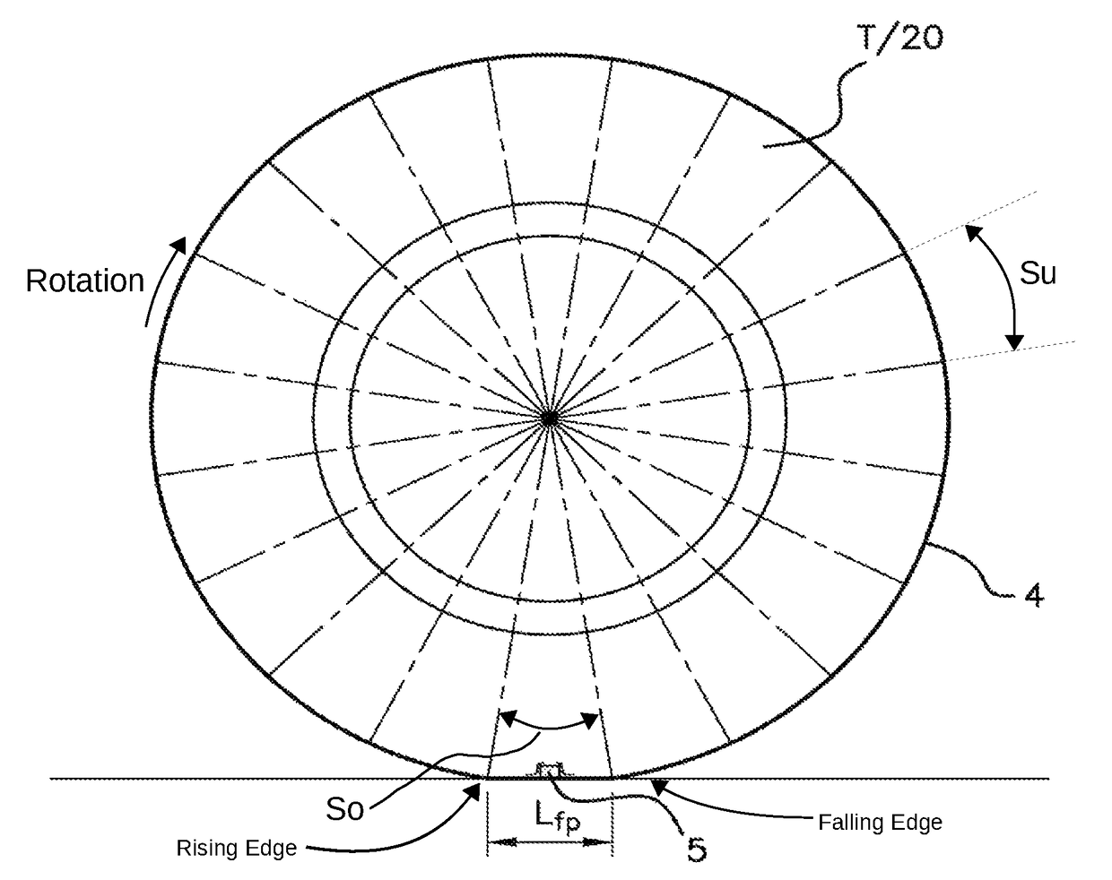
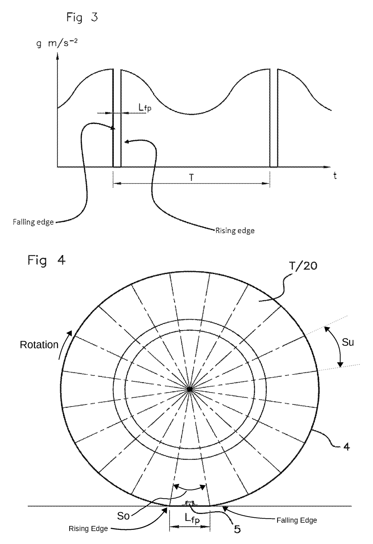
[0033]For the application of the method, as shown in FIG. 1, the vehicle 1 has wheels such as that indicated by 2, each wheel being conventionally composed of a rim 3 fitted with a tire 4, and a system for monitoring parameters, such as pressure or temperature, of each tire 4, including, primarily, an electronic module 5 associated with each of the wheels 2.

[0034]As shown in FIG. 1, each of these electronic modules 5 is positioned on the inner face of the tread 4a of a tire 4. Additionally, in order to allow for servicing, the module is inserted into a flexible receptacle6 bonded onto the tread 4a and made of a plastic material adapted to form a “pouch” of retentive shape in which the electronic module 5 is trapped.

[0035]Additionally, as shown in FIG. 2, each electronic ...


PUM


Abstract

An angular position is determined for an electronic module fixed to the inner face of the tread of a tire fitted to a wheel of a vehicle. A sensor for measuring the radial acceleration of the wheel is integrated into the electronic module, and a variation of the radial acceleration is detected that corresponds to a position of the electronic module when it contacts the ground. This variation is used to determine a frame of reference defined by an origin and a reference unit corresponding to an angular sector of the tire having a length is shorter than a mean length of the footprint of the grounded tire, in order to determine angular positions of the electronic module in the frame of reference.

Description

[0001]The invention relates to a method for determining, during the rotation of a vehicle wheel fitted with a tire, the angular position of an electronic module fixed to the inner face of the tread of said tire.BACKGROUND OF THE INVENTION[0002]It is increasingly common for motor vehicles to have monitoring systems for safety purposes, these systems having sensors mounted on each of the wheels of the vehicle, used for measuring parameters, such as pressure or temperature, of the tires fitted on these wheels, with the aim of informing the driver of any abnormal variation in the measured parameter.[0003]These monitoring systems conventionally have an electronic module mounted on each wheel of the vehicle, incorporating, in addition to the aforesaid sensors, a microprocessor and a radio frequency transmitter, while the system also has a central unit for receiving the signals sent by the transmitters, including a computer incorporating a radio frequency receiver connected to an antenna.[...

Claims


Application Information

Patent Timeline
IPC IPC(8): G01P15/16B60C23/04B60C23/06
CPCG01P15/165B60C23/0416B60C23/0459B60C23/0489B60C23/0493B60C23/064
Inventor GUINART, NICOLASBOISSET, JEAN-PHILIPPE
Owner CONTINENTAL AUTOMOTIVE FRANCE
Features
  • R&D
  • Intellectual Property
  • Life Sciences
  • Materials
  • Tech Scout
  • Unparalleled Data Quality
  • Higher Quality Content
  • 60% Fewer Hallucinations
Learn More