
Heel-lifting elliptical machine

a technology of elliptical machine and elliptical cylinder, which is applied in the direction of gymnastic exercise, frictional force resistor, sport apparatus, etc., can solve the problems of user's feet not being able user's feet not being able to do vertical aerobic exercise, and user's foot not being able to exercise in various ways, so as to reduce obstruction and noise, and increase exercise intensity

Inactive Publication Date: 2017-05-02
HSU KUAN YUNG
View PDF13 Cites 8 Cited by
  • Summary
  • Abstract
  • Description
  • Claims
  • Application Information

AI Technical Summary

Benefits of technology

The present invention provides a heel-lifting elliptical machine that reduces obstacles and noise while increasing exercise intensity. Unlike conventional air walkers that only provide a back-and-forth route, the elliptical machine allows for vertical sliding with a pedal assembly that moves along with the rotation of the driving wheel. This allows for a more challenging and effective work-out. In addition, the elliptical machines of this invention do not require a damper to generate resistance, making it more efficient and effective.

Problems solved by technology

However, because the linkage or the pivot shaft of the conventional stepping machine is mounted with the damper, the user may be directly aware of an obstruction and a noise generated by the damper when stepping on the pedals such that the stepping movement is not smooth.
Besides, a movement route of the conventional stepping machine is simply up and down, and thus the user's feet cannot exercise in various ways.
Though an obstruction and a noise are inconspicuous, the conventional air walker machine merely provides the sliding route in backward and forward directions, so the user cannot do vertical aerobic exercise and the exercise intensity is inadequate.

Method used


Image

  • Heel-lifting elliptical machine
  • Heel-lifting elliptical machine
  • Heel-lifting elliptical machine

Examples


Embodiment Construction

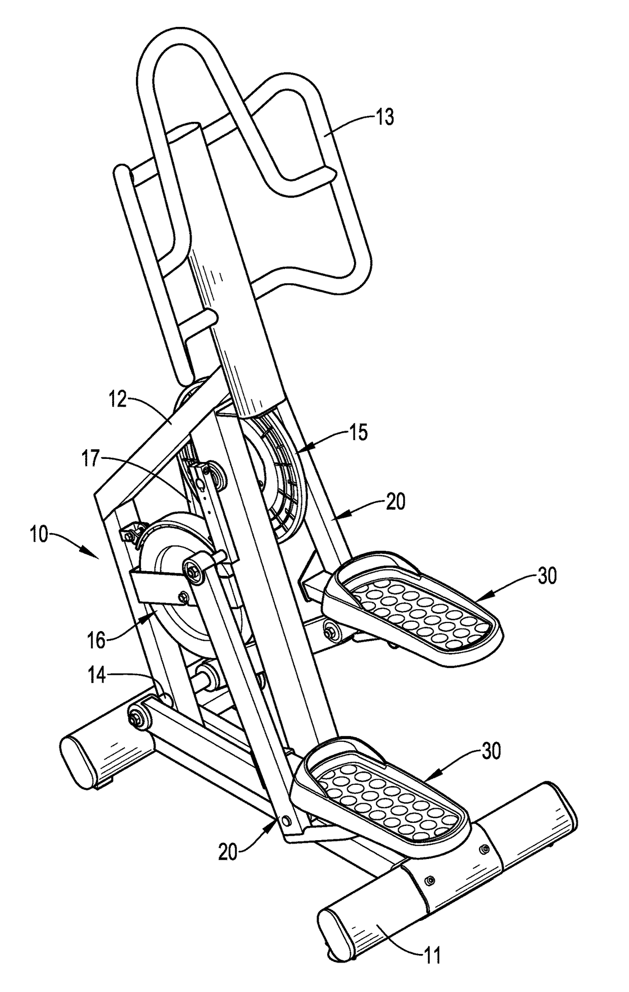
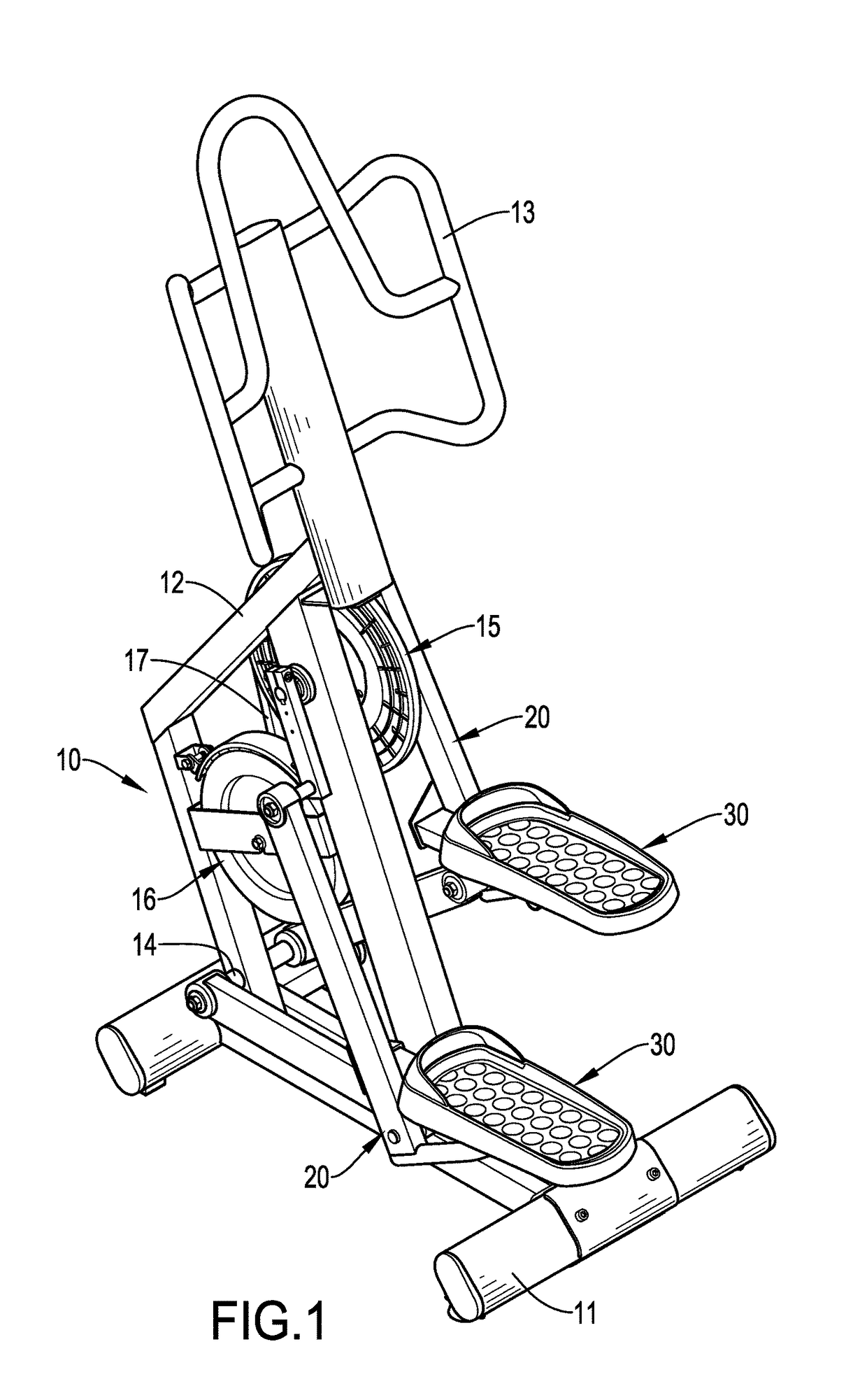
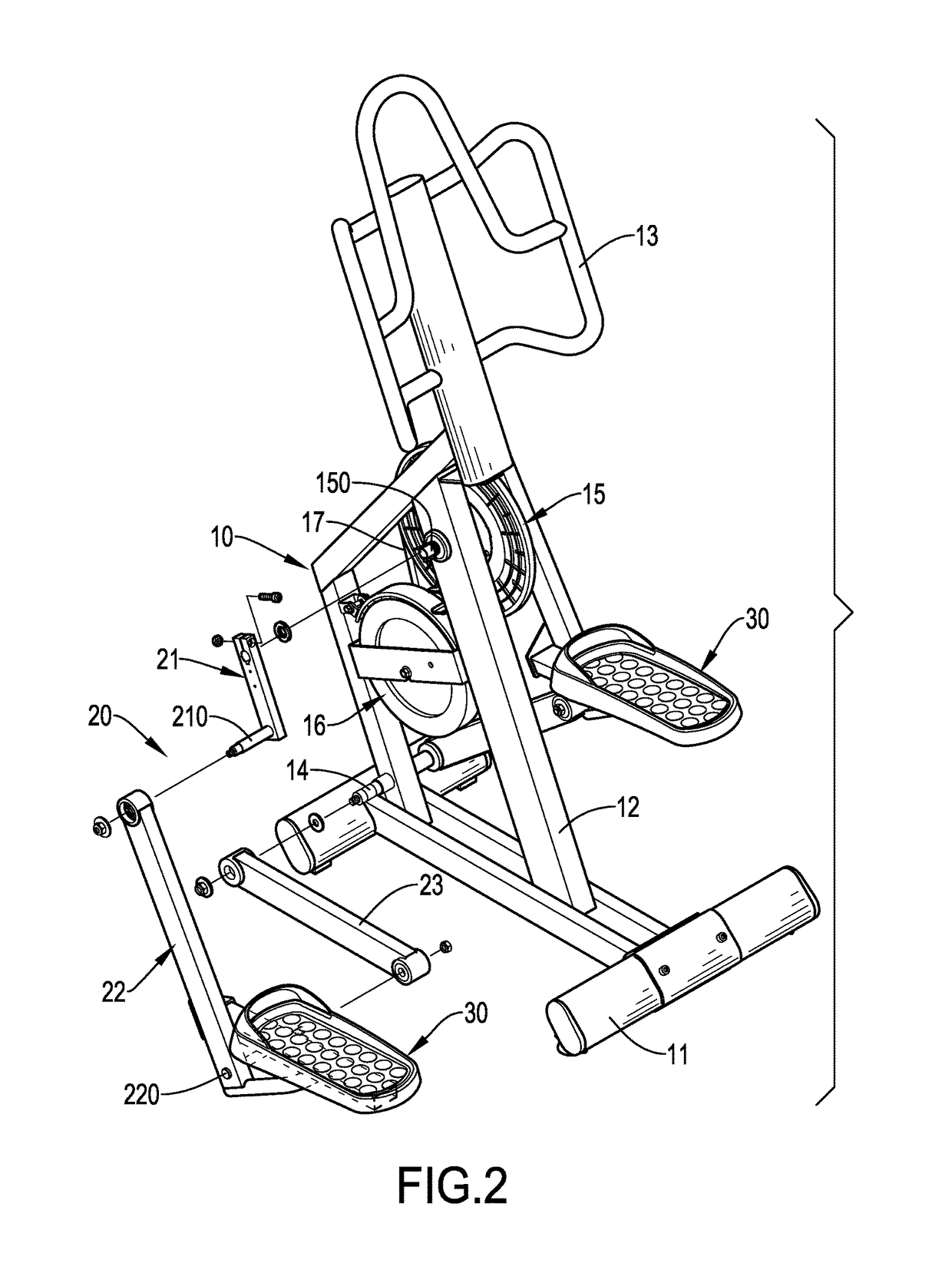
[0043]With reference to FIGS. 1 to 3, a heel-lifting elliptical machine in accordance with a first embodiment of the present invention comprises a foundation 10, two linkage assemblies 20 and two pedal assemblies 30. The foundation 10 forms an H-shaped base portion 11 at a bottom of the foundation 10, a quadrilateral frame portion 12 at a middle of the foundation 10, and a holding portion 13 at an upper portion of the foundation 10. The foundation 10 comprises a swing shaft 14, an uprightly rotatable driving wheel 15, a flywheel 16 and a driving belt 17. The swing shaft 14 is mounted on a lower portion of a front of the frame portion 12. The driving wheel 15 is mounted on an upper portion of a rear of the frame portion 12, and a center of the driving wheel 15 forms a driving shaft 150 which is rotatably mounted through the frame portion 12 of the foundation 10. The flywheel 16 is mounted on a middle of the frame portion 12 and corresponded to the driving wheel 15. The driving belt 1...


PUM


Abstract

A heel-lifting elliptical machine has a foundation, two linkage assemblies and two pedal assemblies. The foundation comprises a swing shaft and a driving wheel connected with a flywheel via a driving belt. The linkage assemblies are mounted on two sides of the foundation, staggered from each other, and joined to a driving shaft of the driving wheel. Each of the linkage assemblies comprises a rotation rod, a crank and a swing arm. The rotation rod is connected to the driving shaft. The crank is pivotably mounted on the other end of the rotation rod. The swing arm is pivotably mounted on the swing shaft and the crank. Two pedal assemblies are mounted securely on the cranks and form vertical ellipse routes along with the movement of the cranks, thereby increasing the exercise intensity and decreasing the obstruction and the noise.

Description

BACKGROUND OF THE INVENTION[0001]1. Field of the Invention[0002]The present invention relates to fitness equipment, especially to a heel-lifting elliptical machine.[0003]2. Description of the Prior Arts[0004]The conventional stepping machine comprises a foundation tiltably mounted with linkages, and the linkages are vertically staggered on the foundation and laterally disposed on two sides of the foundation. A free end of each one of the linkages comprises a pedal. A hydraulic or a pneumatic damper is mounted on a pivot shaft pivoted on the linkage, or a damper is directly mounted on the linkage, such that when the user steps on the pedals right and left alternately and make the linkages swing up and down, the user can exercise through the movement resisted by the damper.[0005]However, because the linkage or the pivot shaft of the conventional stepping machine is mounted with the damper, the user may be directly aware of an obstruction and a noise generated by the damper when steppi...

Claims


Application Information

Patent Timeline
Patent Type & Authority Patents(United States)
IPC IPC(8): A63B22/04A63B23/10A63B23/04A63B22/02A63B23/035
CPCA63B22/04A63B23/03525A63B23/0405A63B23/10A63B21/015A63B21/225A63B21/4047A63B22/0664A63B2022/0682A63B2210/50
Inventor HSU, KUAN-YUNG
Owner HSU KUAN YUNG
Learn More