Device for locking a vehicle seat

a vehicle seat and locking technology, applied in the direction of couplings, vehicles/pulleys, ropes and cables, etc., can solve the problems of not being able to ensure or ensure the effect of an adequate degree, not being able to produce sufficient counterforce, and not being able to always be suitable, so as to improve the impact resistance of the device

Active Publication Date: 2017-05-02
PWO AG
View PDF35 Cites 5 Cited by
  • Summary
  • Abstract
  • Description
  • Claims
  • Application Information

AI Technical Summary

Benefits of technology

[0014]The invention is based on the object of developing a device for locking a vehicle seat of the type mentioned at the beginning to the effect that the impact resistance of the device is improved while ensuring smooth-running during intended opening of the pawl.
[0016]The locking device according to the invention proceeds from the concept of the known locking device of providing a catching surface and a clamping surface on the locking element. As a result, lower demands are imposed on the locking element according to the invention with regard to the manufacturing tolerances. The nevertheless high impact resistance of the locking device according to the invention is now ensured at least also by means of the actuating element in conjunction with the stop. If, in the event of an impact, the pawl exerts a torque on the locking element, which torque acts in the direction of the unlocking position of the locking element, the locking element, during its opening pivoting movement, carries along the actuating element which then, after a short pivoting distance of the locking element, runs against the stop and blocks the further pivoting movement of the locking element. At this point, the clamping surfaces of the locking element and of the pawl are still in contact with each other, and the opening torque which continues to be exerted on the locking element by the pawl does not lead to a further opening movement of the locking element, but rather the clamping surfaces of the locking element and of the pawl come into contact even more intimately with each other, which is especially assisted by the projection on the pawl and the softer material of the locking element in the region of the clamping surface. In this case, the forces are partially absorbed by the stop and partially by the clamping surfaces and are therefore distributed favorably over a plurality of points of the locking device. In the event of an impact, the clamping surface of the pawl can very intimately become wedged with or buried into the clamping surface of the locking element, in particular in the pivoting position of the locking element, in which the actuating element is in contact with the stop, thus avoiding further pivoting of the locking element in the direction of its unlocking position. Owing to the fact that the locking element is softer in the region of the second clamping surface than the pawl in the region of the first clamping surface, the projection of the pawl can bore into the clamping surface of the locking element in the event of high opening torques which the pawl may exert on the locking element in the event of an impact, as a result of which, in the event of an impact, a form-fitting connection is produced between the clamping surface of the locking element and the clamping surface of the pawl, said form-fitting connection reliably avoiding opening of the pawl in the event of an impact.
[0018]For the intentional opening of the pawl, the actuating element is accordingly actuated, which first of all brings about a relative movement between the actuating element and the locking element, to be precise by the limited movement clearance, as a result of which the actuating element is displaced relative to the fixed stop in such a manner that, upon further movement of the actuating element, said actuating element runs past the stop, carrying along the locking element, and can therefore transfer the locking element completely into the unlocking position. The smooth-running of the locking device according to the invention is therefore likewise provided.
[0020]It is advantageous in this case that, during an intended opening of the pawl, a sufficient torque can be exerted by the actuating element on the locking element in order to transfer the locking element into the unlocking position, as a result of which the locking device according to the invention can be opened smoothly.
[0022]While the relative movement between the actuating element and the locking element can also be provided by means of a connection permitting a translatory movement between the actuating element and the locking element, the abovementioned configuration has the advantage of guidance, which can be realized more easily, of the actuating element during its movement relative to the locking element.

Problems solved by technology

Firstly, the pawl must not automatically open during the operation of the vehicle in which the vehicle seat is installed.
However, in the event of an impact of the vehicle during an accident, high forces may act on the pawl and may exert a torque on the pawl in the direction of its open position.
However, the previously mentioned self-locking of the engagement of the two clamping surfaces of the pawl and of the locking element counteracts such a smooth-running actuation of the locking element for opening the pawl, and therefore a construction of the locking device with self-locking bearing of the clamping surface of the locking element against the clamping surface of the pawl is only partly suitable.
The configuration of the known locking device with a locking element, the clamping surface of which bears against the clamping surface of the pawl without self-locking, has the disadvantage that, in order to compensate for play, so as to avoid rattling of the device during operation, a sufficiently large counterforce always has to be produced in order to keep the device, i.e. more precisely the pawl, closed, which has to be realized, for example, by means of a sufficiently high spring force.
Accordingly, the stop has to be designed for absorbing very high forces, but, due to the fact that the stop has to absorb all of the opening forces, this cannot always be ensured or ensured to an adequate degree.

Method used


Image

  • Device for locking a vehicle seat
  • Device for locking a vehicle seat
  • Device for locking a vehicle seat

Examples


Embodiment Construction

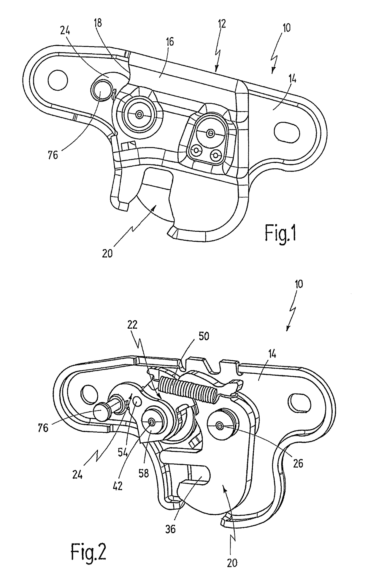
[0037]FIGS. 1 to 6 illustrate a device, which is provided with the general reference number 10, for locking a vehicle seat. The device 10 serves in particular for anchoring a vehicle seat on the floor of a vehicle body.

[0038]FIG. 1 shows the device 10 with a housing12 which has a housing part 14 and a housing part 16. The housing part 16 is illustrated broken away along an edge 18 in FIG. 1. FIG. 2 only illustrates the housing part 14 while the housing part 16 is omitted.

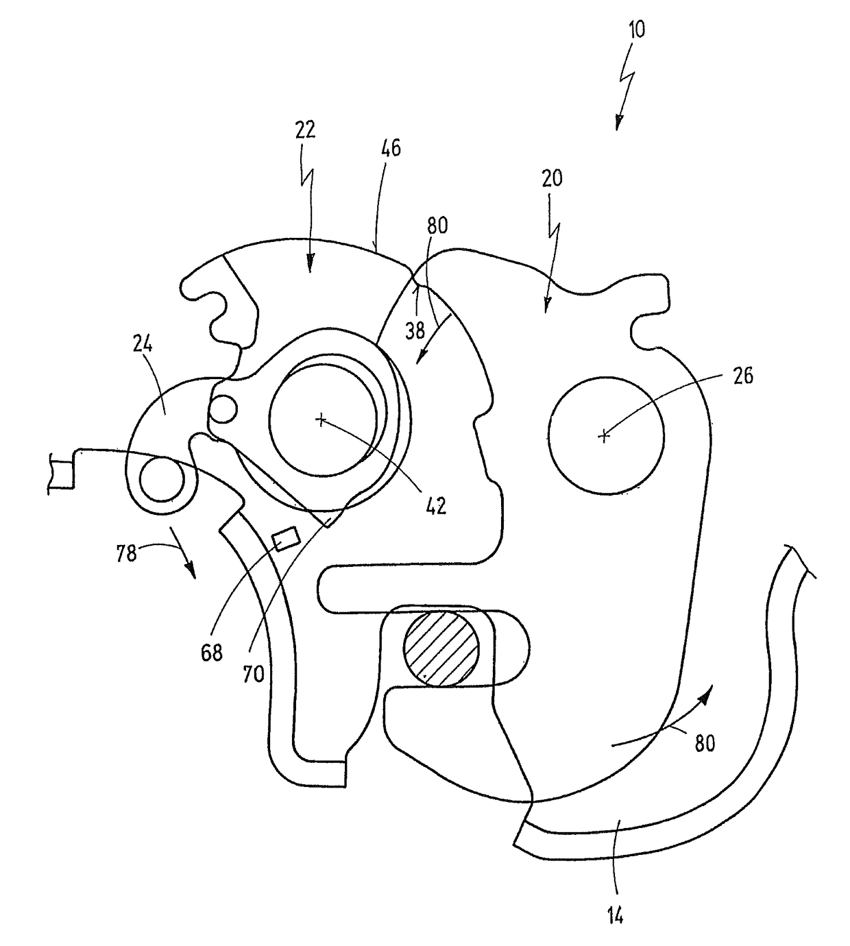
[0039]A pawl 20, a locking element 22 and an actuating element 24, which are described in more detail below, are arranged in the housing 12.

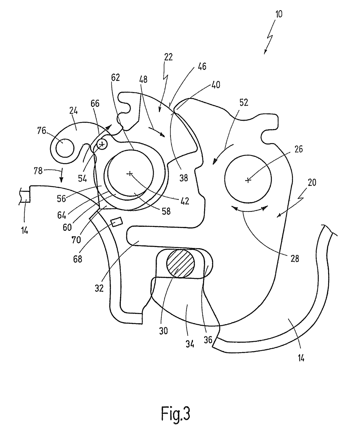
[0040]The pawl 20 can be pivoted about a pivot axis 26, as indicated by a double arrow 28.

[0041]In its closed position shown, for example, in FIG. 3, the pawl 20 is in engagement with a positionally fixed fitting 30 (not illustrated in FIGS. 1 and 2). The fitting 30 is, for example, a bolt which is fixedly connected to the vehicle body and does not belong to the device 10. Corre...


PUM


Abstract

A device for locking a vehicle seat has a pawl which can be pivoted about a first pivot axis and, in a closed position, is in engagement with a positionally fixed fitting and, in an open position, is free from the fitting, wherein the pawl has a first clamping surface, furthermore a locking element for locking the pawl in the closed position, which locking element can be pivoted about a second pivot axis and has a second clamping surface which, in a locking position, bears against the first clamping surface and, in the process, keeps the pawl in the closed position, and, in an unlocking position, is free from the first clamping surface, and an actuating element which interacts with the locking element in order to transfer the locking element into the unlocking position. A stop is provided for the actuating element in such a manner that, upon action of a torque exerted by the pawl on the locking element, the actuating element interacts in a blocking manner with the stop and blocks the further movement of the locking element before the latter reaches the unlocking position. In the region of the second clamping surface, the locking element has a material which is softer than a material which the pawl has in the region of the first clamping surface, and the pawl has a projection on which the first clamping surface is at least partially formed.

Description

CROSS REFERENCE TO RELATED APPLICATIONS[0001]The present application is a continuation of International Patent Application PCT / EP 2007 / 009746 filed on Nov. 10, 2007 designating the United States, which was published in the German language and claims priority of German Patent Application No. 10 2006 058 891.6 filed on Dec. 4, 2006. The entire contents of these applications are incorporated herein by reference.BACKGROUND OF THE INVENTION[0002]The invention generally relates to devices for locking a vehicle seat.[0003]More specifically, the invention relates to a device for locking a vehicle seat of the type comprising a pawl which can be pivoted about a pivot axis and, in a closed position, is in engagement with a positionally fixed fitting and, in an open position, is free from the fitting, and a locking element for locking the pawl in the closed position.[0004]Without limiting the general character, the locking device mentioned at the beginning can be used for anchoring a vehicle se...

Claims


Application Information

Patent Timeline
Patent Type & Authority Patents(United States)
IPC IPC(8): B25G3/18F16B21/00F16D1/00B60N2/015
CPCB60N2/01583Y10T403/581Y10T403/591F16B2200/69
Inventor SEIGEL, JUERGENOBRECHT, JOHANNESROHLFING, ANDREASSCHWARTZ, ANDREAS
Owner PWO AG
Why Eureka
Try Eureka