Front-end structure of a motor vehicle

a front-end structure and motor vehicle technology, applied in bumpers, propulsion parts, transportation and packaging, etc., can solve the problems of increased air resistance, influence on fuel consumption, and insufficient configuration of air distribution in other operating situations, so as to reduce the air resistance of the motor vehicle and reduce the effect of air resistan

Active Publication Date: 2017-05-02
DR ING H C F PORSCHE AG
View PDF31 Cites 7 Cited by
  • Summary
  • Abstract
  • Description
  • Claims
  • Application Information

AI Technical Summary

Benefits of technology

[0006]It would be advantageous to provide a front-end structure of a motor vehicle, which front-end structure realizes an improved air distribution for the cooling and for the reduction in air resistance.

Problems solved by technology

Said air flow exerts air resistance on the body, which air resistance is in part also responsible for the fuel consumption of the motor vehicle.
The wheels, which are typically arranged in the wheel arches and which rotate when the motor vehicle is travelling, generate air turbulence laterally with respect to the wheel arches, which turbulence increases the air resistance, which in turn has an influence on fuel consumption.
A design of the flow ducts which is adapted to one specific operating situation has the effect that the air distribution is not optimally configured in other operating situations.

Method used


Image

  • Front-end structure of a motor vehicle
  • Front-end structure of a motor vehicle
  • Front-end structure of a motor vehicle

Examples


Embodiment Construction

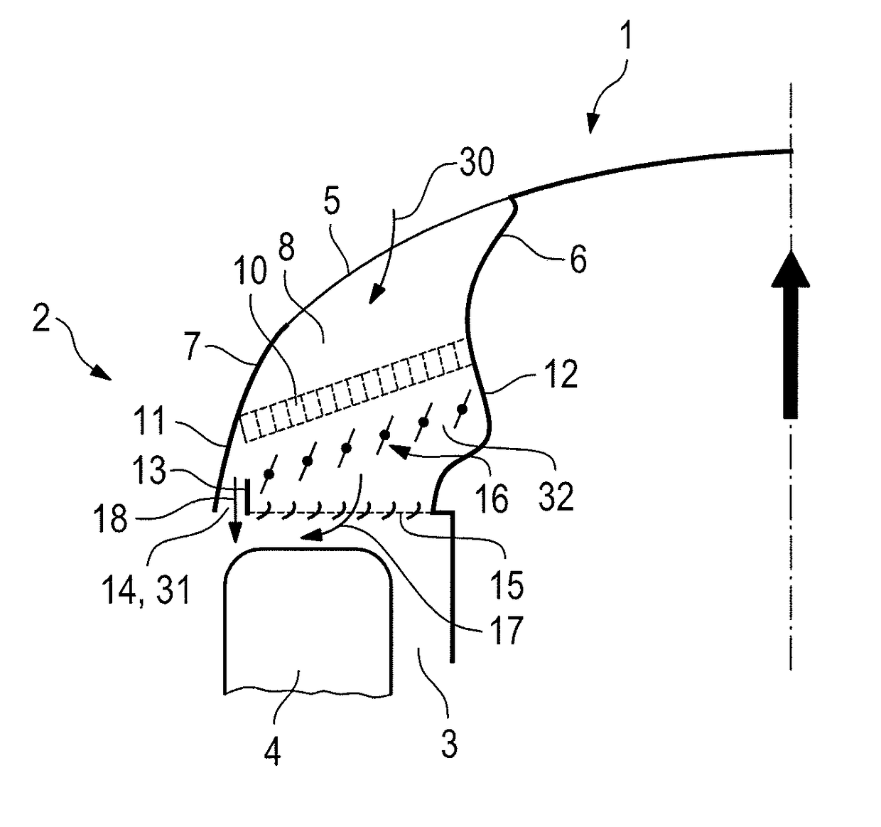
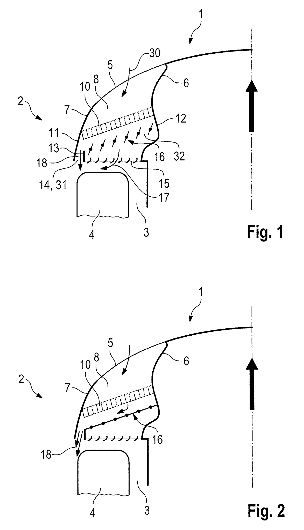
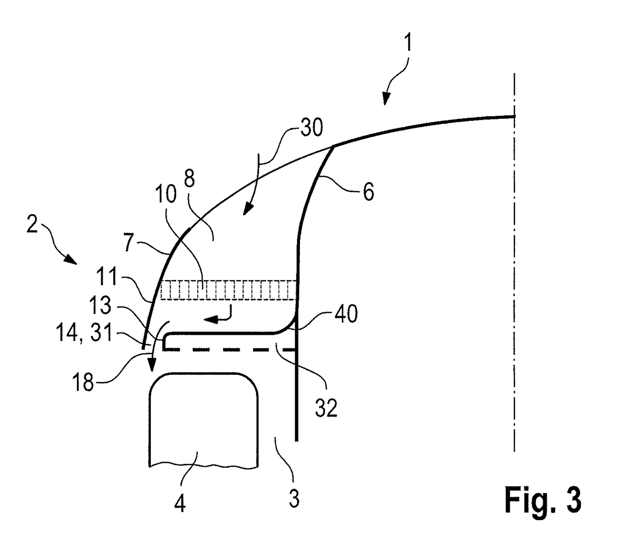
[0028]FIG. 1 shows, in a partial view, the left-hand part of a front-end structure 1 of a motor vehicle 2 with wheel arch 3 and with a wheel 4 arranged therein.

[0029]In the front-end structure 1, there is provided an air inlet opening 5 which is arranged in particular in the bumper or elsewhere and which is delimited by an encircling wall 6 with a laterally arranged air-guiding element 7. An air duct 8 is provided so as to extend from the air inlet opening 5. The air duct 8 has a heat exchanger 10 arranged therein, through which heat exchanger the air flows, as per arrow 30. Downstream of the heat exchanger 10, the air duct 8 divides into a first duct part 31 and a second duct part 32.

[0030]The second duct part 32 leads, by way of its air outlet opening 15, into the wheel arch 3. Arranged adjacent to the second duct part is the first duct part 31, which is arranged on the outer side of the second duct part. Both the first and the second duct parts 31, 32 branch off from the air duct...


PUM


Abstract

A front-end structure of a motor vehicle, having an air inlet opening and having an air duct which extends from the air inlet opening and in which there is arranged a heat exchanger through which air can flow, wherein the air duct conducts an air flow into the wheel arch and / or laterally with respect to the wheel arch, wherein the air duct is divided, downstream of the heat exchanger, into a first duct part and a second duct part, wherein the first duct part conducts air laterally with respect to the wheel arch and the second duct part conducts air into the wheel arch, wherein an air flow control device is provided in the air duct, which air flow control device controls the air flow through the first duct part and / or through the second duct part.

Description

CROSS-REFERENCE TO RELATED APPLICATIONS[0001]This application claims priority to German Patent Application No. DE 10 2014 118 800.4, filed Dec. 17, 2014, which is incorporated by reference herein in its entirety.FIELD OF THE INVENTION[0002]The invention relates to a front-end structure of a motor vehicle.BACKGROUND OF THE INVENTION[0003]Motor vehicles have a vehicle body with a front-end structure and a rear-end structure, said vehicle body being exposed to the air flow when the motor vehicle is in motion. Said air flow exerts air resistance on the body, which air resistance is in part also responsible for the fuel consumption of the motor vehicle. The wheels, which are typically arranged in the wheel arches and which rotate when the motor vehicle is travelling, generate air turbulence laterally with respect to the wheel arches, which turbulence increases the air resistance, which in turn has an influence on fuel consumption.[0004]FR 2 858 796 A1, which is incorporated by reference ...

Claims


Application Information

Patent Timeline
Patent Type & Authority Patents(United States)
IPC IPC(8): B60K11/04B62D35/00B60K11/08B62D25/16
CPCB62D35/00B60K11/04B60K11/08B60K11/085B62D25/16B60R19/48B62D35/005Y02T10/88
Inventor WOLF, THOMAS
Owner DR ING H C F PORSCHE AG
Why Eureka
Try Eureka