Driving force transmission device

a transmission device and driving force technology, applied in the direction of clutches, mechanical actuated clutches, non-mechanical actuated clutches, etc., can solve the problems of increasing cost, increasing cost, increasing cost, etc., and achieve the restriction of the rotation amount of the second cage relative to the holding plate, preventing the second cage from rotating excessively, and the effect of reducing the rotation amoun

Active Publication Date: 2017-05-02
JTEKT CORP
View PDF11 Cites 1 Cited by
  • Summary
  • Abstract
  • Description
  • Claims
  • Application Information

AI Technical Summary

Benefits of technology

[0014]The present invention provides a driving force transmission device which can switch between transmission and disconnection of a rotational driving force between a first shaft body and a second shaft body with a simple structure and which can reduce cost accordingly. Further, the present invention provides a driving force transmission device which can restrict an amount of relative movement of first and second cages and which can prevent excessive rotation of one of the first and second cages accordingly. Further, the present invention provides a driving force transmission device which can maintain a high running torque applied to first and second cages at an initial stage of drawing by an electromagnetic clutch and which can successfully switch between transmission and disconnection of a rotational driving force accordingly. Further, the present invention provides a driving force transmission device which can prevent excessive rotation of at least one of first and second cages.

Problems solved by technology

This complicates a shape of the rotational cage, which causes an increase in cost.
This also causes an increase in cost.
The cam can be formed by use of ceramic rather than a steel material, but this also leads an increase in cost.
As a result, the one of the first and second cages may rotate excessively by a rotation amount more than an expected rotation amount.
In a case where one of the cages has difficulty in rotating and the other one of the cages smoothly rotates without any problems, when the guide member moves toward the axial first side due to the drive of the electromagnetic clutch, the rotation of the cage (the first cage in the above example) that does not have difficulty in rotating may rotate excessively by a rotation amount more than an expected rotation amount.

Method used


Image

  • Driving force transmission device
  • Driving force transmission device
  • Driving force transmission device

Examples


Embodiment Construction

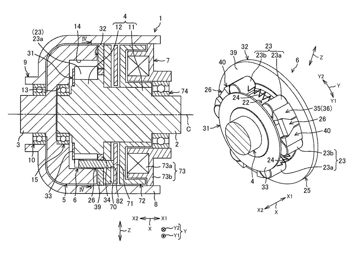
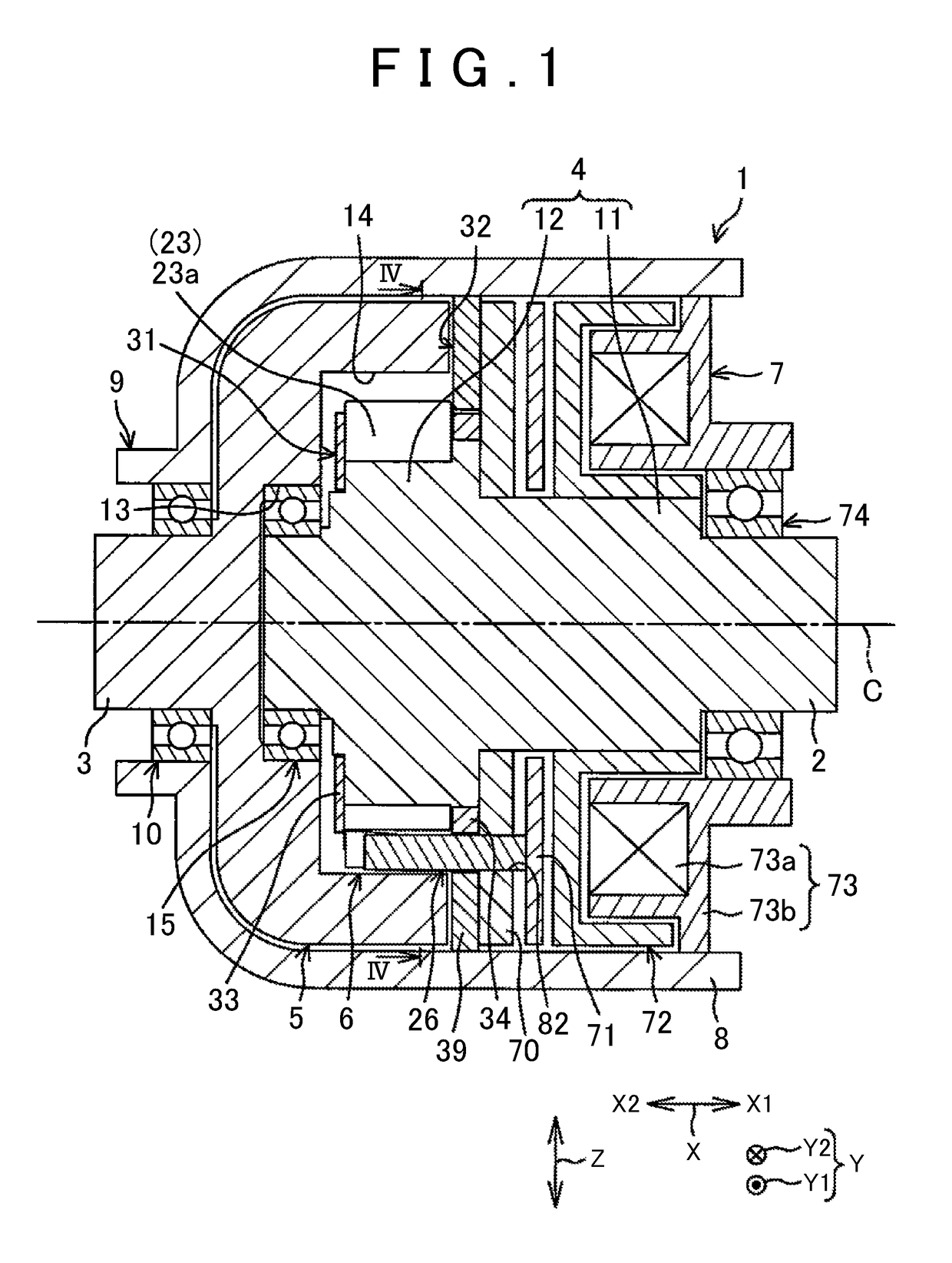
[0104]The following describes a first embodiment of the present invention in detail with reference to the attached drawings. FIG. 1 is a sectional view of a driving force transmission device 1 according to a first embodiment of the present invention. The driving force transmission device 1 is a device that can switch between transmission and disconnection of a rotational driving force (a running torque) between a first shaft body 2 and a second shaft body 3 placed coaxially. The driving force transmission device 1 includes: an inner ring 4 coaxially and integrally connected to the first shaft body 2 serving as an input shaft; an outer ring 5 coaxially and integrally connected to the second shaft body 3 serving as an output shaft; a two-way clutch 6 that performs transmission / disconnection of a rotational driving force from the inner ring 4 to the outer ring 5; an electromagnetic clutch 7 that performs fastening / release of the two-way clutch 6; and a housing 8 that accommodates there...


PUM


Abstract

A driving force transmission device includes an inner ring; an outer ring; a roller pair constituted by a first roller and a second roller; an elastic member; a first cage including a first pressing portion; a second cage including a second pressing portion; a first guide member; a second guide member; and an electromagnetic clutch including an armature connected to the first and second guide members. Along with rotation of the first cage toward the circumferential second side, the first pressing portion presses the first roller toward the circumferential second side. Along with rotation of the second cage toward the circumferential first side, the second pressing portion presses the second roller toward the circumferential first side.

Description

INCORPORATION BY REFERENCE[0001]The disclosure of each of Japanese Patent Applications No. 2014-253268, 2015-004416, 2015-005955, and 2015-034377 respectively filed on Dec. 15, 2014, Jan. 13, 2015, Jan. 15, 2015, and Feb. 24, 2015 including the specification, drawings and abstract is incorporated herein by reference in its entirety.BACKGROUND OF THE INVENTION[0002]1. Field of the Invention[0003]The present invention relates to a driving force transmission device that can switch between transmission and disconnection of a rotational driving force between a first shaft body and a second shaft body.[0004]2. Description of Related Art[0005]A rotation transmission device described in Japanese Patent Application Publication No. 2013-92191 (JP 2013-92191 A) includes an electromagnetic clutch, and a roller clutch as a two-way clutch. The roller clutch is configured such that a pair of opposed rollers, and a spring that urges the rollers in directions away from each other are placed in each ...

Claims


Application Information

Patent Timeline
Patent Type & Authority Patents(United States)
IPC IPC(8): F16D27/102F16D15/00F16D27/14F16D27/10
CPCF16D27/102F16D15/00F16D27/10F16D27/14
Inventor YAMATANI, TOMOYAARAMOTO, GENTOOKUMURA, TSUYOSHI
Owner JTEKT CORP
Why Eureka
Try Eureka