Portable electronic device with an antenna array and method for operating same

a portable electronic device and antenna array technology, applied in the field of antenna arrays in portable electronic devices, can solve the problems of significant gain reduction, difficult to meet phase and amplitude control requirements, and difficult to incorporate multiple antenna elements into the antenna array

Active Publication Date: 2017-05-02
MOTOROLA MOBILITY LLC
View PDF15 Cites 35 Cited by
  • Summary
  • Abstract
  • Description
  • Claims
  • Application Information

AI Technical Summary

Problems solved by technology

However, due to space constraints in portable devices, it is difficult to incorporate multiple antenna elements to form the antenna array.
Additionally, positioning the antenna array so that it concentrates radiation of radio waves towards a wearer's hand or other body pa

Method used


Image

  • Portable electronic device with an antenna array and method for operating same
  • Portable electronic device with an antenna array and method for operating same
  • Portable electronic device with an antenna array and method for operating same

Examples


Embodiment Construction

[0022]Generally speaking, pursuant to various embodiments, described herein are an antenna array for a portable electronic device, such as a wearable electronic device, and a method for operating the antenna array to concentrate radiation of radio waves through a sidewall of the portable electronic device.

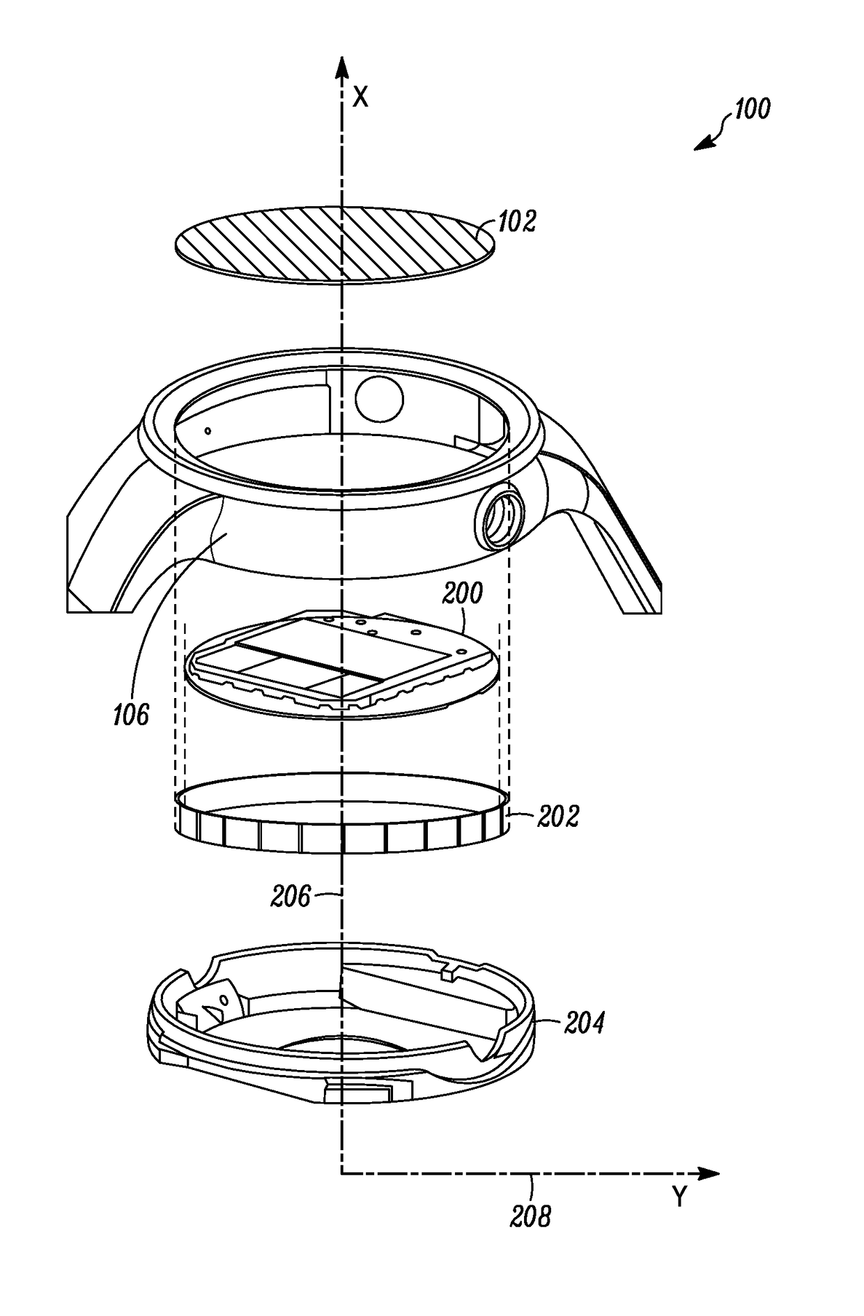
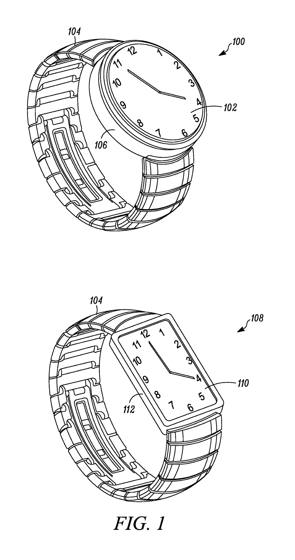
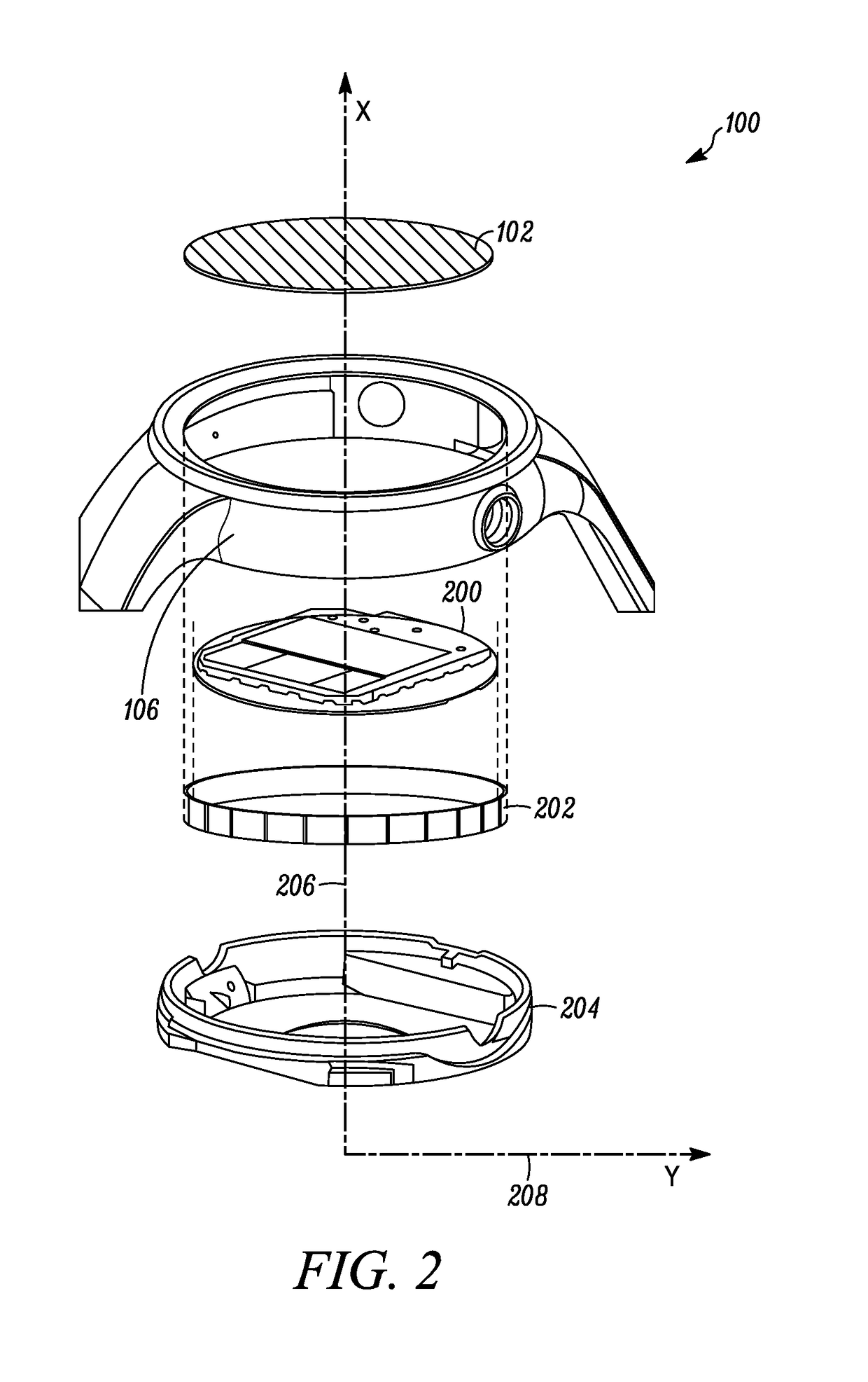
[0023]FIG. 1 illustrates a representative wearable electronic device 100 in which embodiments of an antenna array can be implemented. The wearable electronic device 100 includes a device housing having a shape and a sidewall 106 and a device face 102 coupled to the device housing. Illustratively, a cross-section of the device housing is in a shape of a closed-plane curve which, in this case, is circular. A “closed-plane curve” is defined herein as a line that is bent around until its ends join together. Examples of closed-plane curves are circles, ellipses, and ovals. The wearable electronic device 100 further includes a wearable element 104, in this case a wristband, attached to t...


PUM


Abstract

Apparatus includes a device housing, a device face, a printed circuit board (PCB), and an antenna array. The device housing has a shape characterized by an axis, a planar housing surface that is perpendicular to the axis, and a housing sidewall that is parallel to the axis. The housing sidewall is positioned along a periphery of a planar housing surface. The device face is positioned at an opposite end of the device housing from the planar housing surface. The PCB is positioned between and parallel to the planar housing surface and the device face. The antenna array has multiple antenna elements at least some of which are electrically coupled to the PCB. The antenna array is configured to concentrate radiation of radio waves laterally through a radiation plane that is parallel to the sidewall of the housing and that is perpendicular to the device face and the planar housing surface.

Description

FIELD OF THE DISCLOSURE[0001]The present disclosure relates generally to antenna arrays in portable electronic devices and more particularly to antenna arrays that concentrate radiation of radio waves through a sidewall of a portable electronic device.BACKGROUND[0002]5th Generation (“5G”) mobile communications depend on millimeter-wave frequencies (e.g., >24 GHz). Generally, to establish a wireless link at millimeter-wave frequencies in portable devices, there are few, if any, alternatives other than using an antenna array. However, due to space constraints in portable devices, it is difficult to incorporate multiple antenna elements to form the antenna array. For example, positioning the antenna array, in the device, so that it concentrates radiation of radio waves towards a device display can cause significant gain reduction due to interference with the device display and intermediary device components. Additionally, positioning the antenna array so that it concentrates radiati...

Claims


Application Information

Patent Timeline
IPC IPC(8): H04M1/00H01Q1/27H04B1/3827
CPCH01Q1/273H04B1/385H01Q1/38H01Q13/02H01Q21/0012H01Q21/20H01Q21/28
Inventor ISLAM, MDRUSSELL, MICHAEL
Owner MOTOROLA MOBILITY LLC
Why Eureka
Try Eureka