
Electrical connector

a technology of electrical connectors and connectors, applied in the direction of electrical apparatus, connection, coupling device connection, etc., can solve the problems of affecting the transmission quality of original signals, affecting and the lower wire rb>2/b> at the gap s cannot form an effective shielding by the circuit board, so as to simplify the design of electrical connectors and facilitate configuration and use. , to achieve the effect of maintaining the stability of signal transmission

Active Publication Date: 2017-05-02
UNICONN CORP
View PDF14 Cites 15 Cited by
  • Summary
  • Abstract
  • Description
  • Claims
  • Application Information

AI Technical Summary

Benefits of technology

The present invention provides an electrical connector with a low profile that achieves signal shielding. The invention uses a thin shielding portion between the upper and lower wire sets, which eliminates the need for a whole circuit board to be sandwiched between the wire sets. Ground wires are formed through the shielding portion for better signal shielding, and the wire sets are linearly aligned and connected to the contact points, preventing any variation in the thickness of the overall electrical connector. Compared to prior art where the circuit board is sandwiched, the invention is easier to configure and use.

Problems solved by technology

As a result, while transmitting signals, it is easy to be affected by noise.
Since a gap S is inevitably occurred between the backend of the circuit board and the wires during manufacture, the exposing portion of the upper wire R1 and the lower wire R2 at the gap S cannot form an effective shield by the circuit board.
Therefore, the signals transmitted by the upper wire R1 and the lower wire R2 will interfere with each other and the signal interference (CROSSTALK) occurs, which affects the transmission quality of the original signals.
However, this configuration leads to a multilayer structure due to the circuit board being sandwiched between the upper wire and the lower wire.
The core wires have to be pre-processed and shaped in advance, resulting increase of working hours and uncertainty.
Additionally, the thickness of the core wires is also increased considerably, which causes the volume of final product increased to be unfavorable for usage.

Method used


Image

  • Electrical connector
  • Electrical connector
  • Electrical connector

Examples


Embodiment Construction

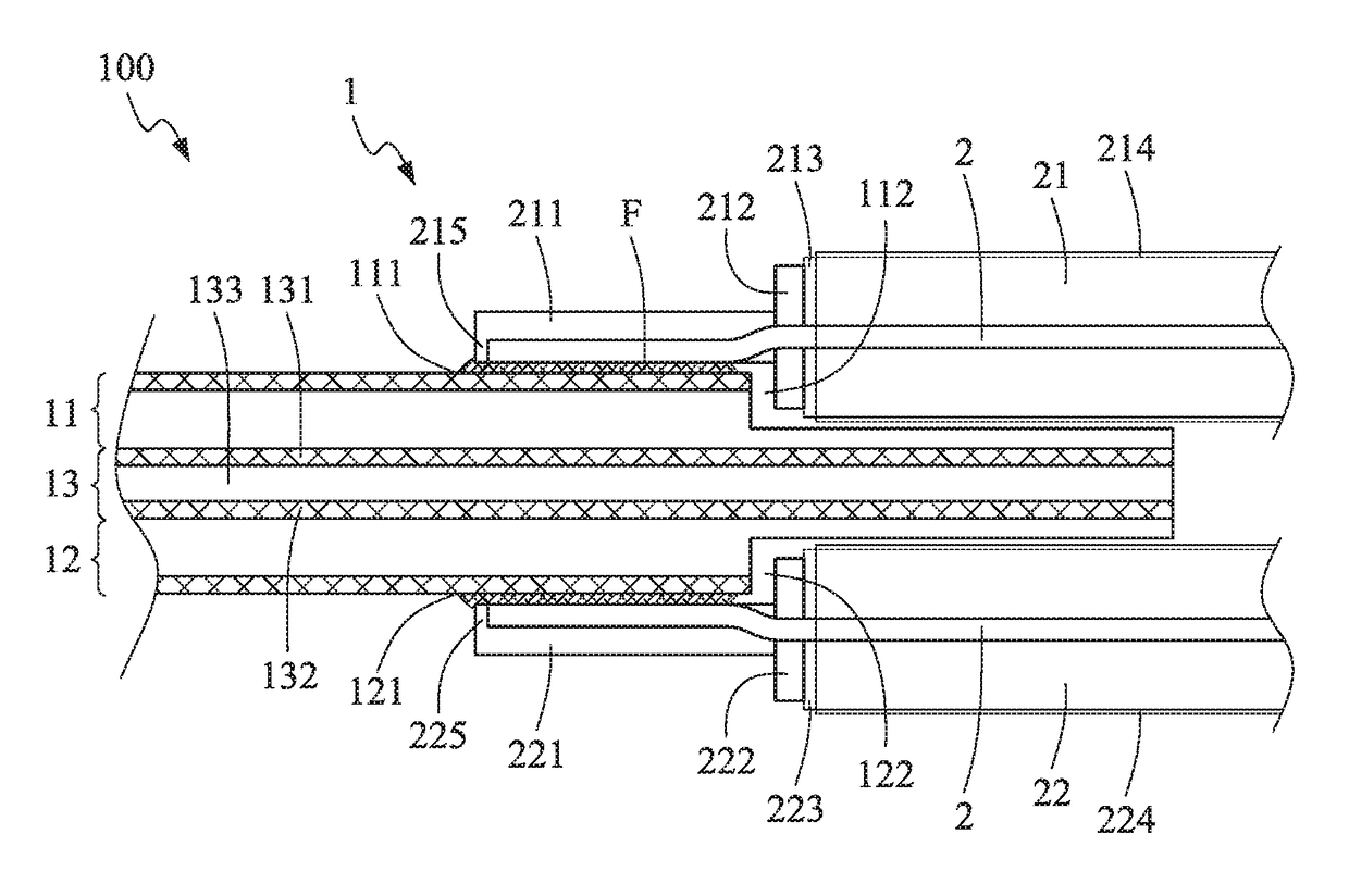
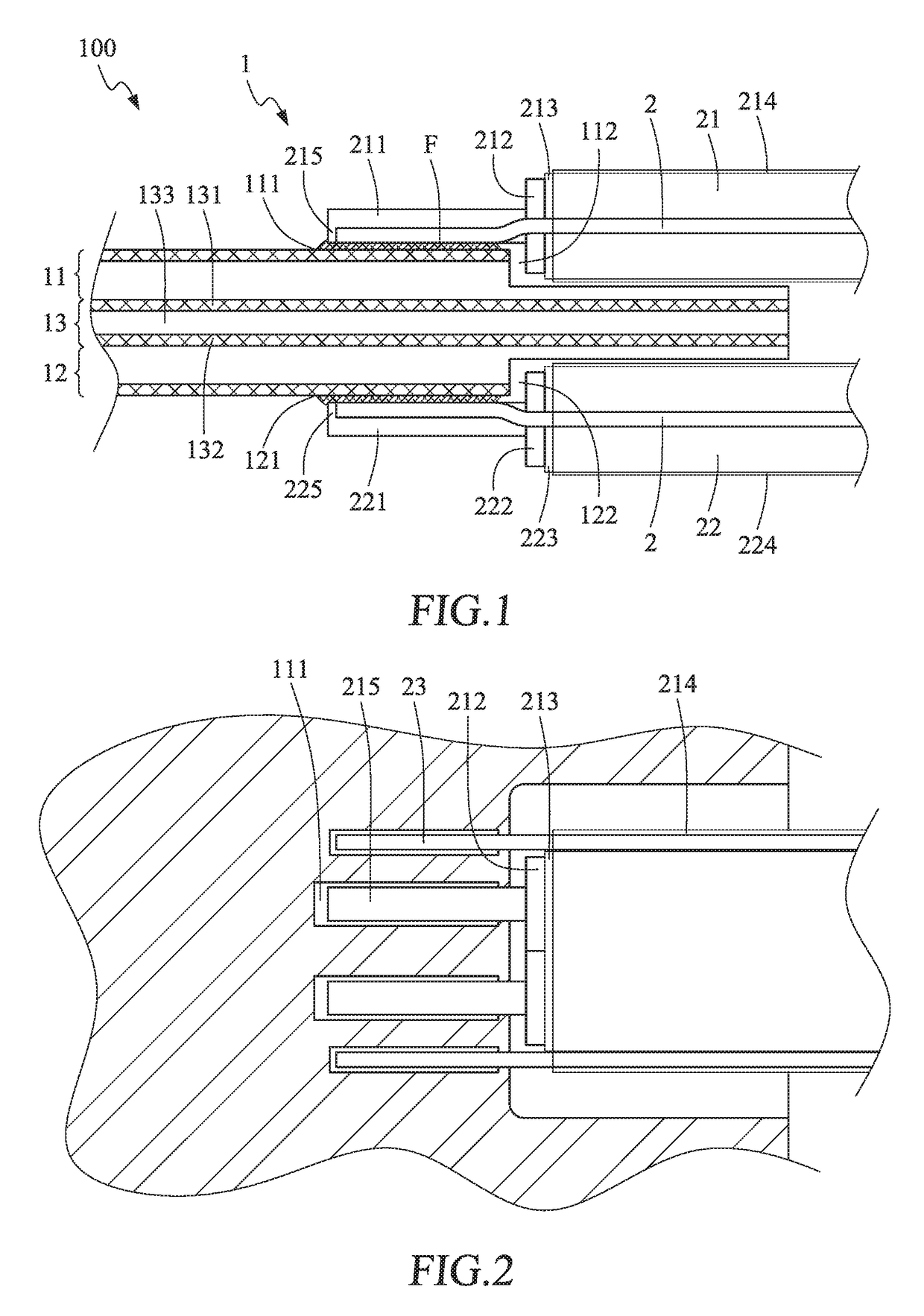
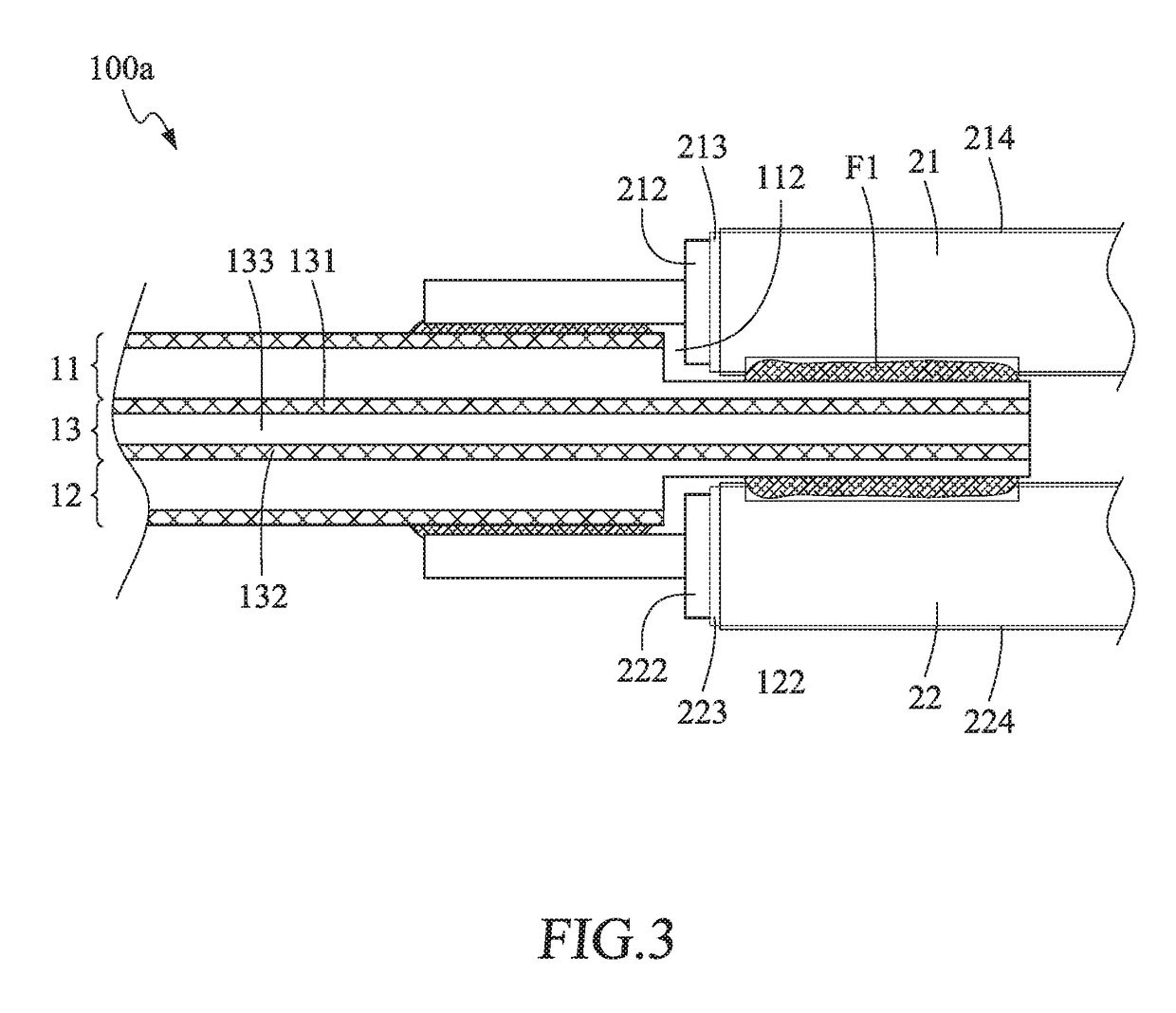
[0018]The embodiments of the present invention are described below with reference to FIG. 1 to FIG. 3. The description is for describing the preferred embodiments of the present invention, and is not intended to limit the way of embodying the present invention.

[0019]As shown in FIG. 1 and FIG. 2, an electrical connector according to a first embodiment of the present invention comprises a circuit board 1 and a connecting wire member 2.

[0020]As shown in FIG. 1 and FIG. 2, the circuit board 1 includes an upper circuit layer 11, a lower circuit layer 12, and a shielding layer 13. In this embodiment, the circuit board 1 is a double-sided printed circuit board (PCB). Certainly, the invention is not limited to this. In other embodiments, the circuit board 1 is a multilayer printed circuit board. The upper circuit layer 11 is a circuit printed on the upper surface of the circuit board 1. The outer surface of the upper circuit layer 11 has an upper contact point 111, and the outer surface of...


PUM


Abstract

An electrical connector provided in the present invention comprises a circuit board and a connecting wire member. The circuit board includes an upper circuit layer, a lower circuit layer, and a shielding layer. The connecting wire member includes a plurality of upper wires and a plurality of lower wires. The upper circuit layer has an upper concave portion made by removing circuit, and the lower circuit layer has a lower concave portion made by removing circuit. The upper wire set is disposed in the upper concave portion, and the lower wire set is disposed in the lower concave portion. Thus, the shielding between the upper wire set and the lower wire set is achieved, and the assembling and processing of wires and circuit layer is easier.

Description

FIELD OF THE INVENTION[0001]The present invention relates to an electrical connector, and more particularly to an electrical connector, configured with low profile, achieving an effect of signal shielding.BACKGROUND OF THE INVENTION[0002]The electrical connector is a device electrically connected to circuit boards, electronic components or electronic products. With personal computers, personal digital assistants (PDA), smart phones and tablet personal computers and other digital electronic devices are going popular, the electrical connector has become an indispensable intermedium for signal transmission in our daily life. In recent years, a Low Voltage Differential Signal (LVDS) connector has become apparent, which transmits data by very low voltage amplitude and high-speed differential, and has the advantages of low power consumption and low error rate.[0003]However, the frequency of this type of high-speed connectors is usually up to several GigaHertz (GHz) when signals are being ...

Claims


Application Information

Patent Timeline
Patent Type & Authority Patents(United States)
IPC IPC(8): H01R9/05H01R13/6461
CPCH01R13/6461H01R12/53H01R13/6471H01R13/65914
Inventor WANG, CHIH-SHOU
Owner UNICONN CORP
Learn More