
Automatic pupillary distance measurement system and measuring method

a technology of automatic measurement and pupillary distance, applied in the field of automatic measurement of pupillary distance, can solve the problems of unsatisfactory or inadequate measurement accuracy of pupillary distance, poor overall user experience, and inconvenient use, so as to achieve more precise and robust pd measurement results, convenient and more accurate use, and satisfactory overall user experience.

Active Publication Date: 2017-05-09
ULSEE
View PDF11 Cites 0 Cited by
  • Summary
  • Abstract
  • Description
  • Claims
  • Application Information

AI Technical Summary

Benefits of technology

The invention provides an automatic system and method for measuring the distance between a user's pupils and the edge of a credit card. The system provides guidance for the user to properly position their face and the credit card, and obtains a precise measurement with minimal manual effort. The system is convenient and provides a better user experience compared to existing methods.

Problems solved by technology

Meanwhile, people have recognized that automatic extraction of (eye) pupils' features and the card edges of the credit card for various users under different environments using computer vision technology today can lead to many issues and difficulties.
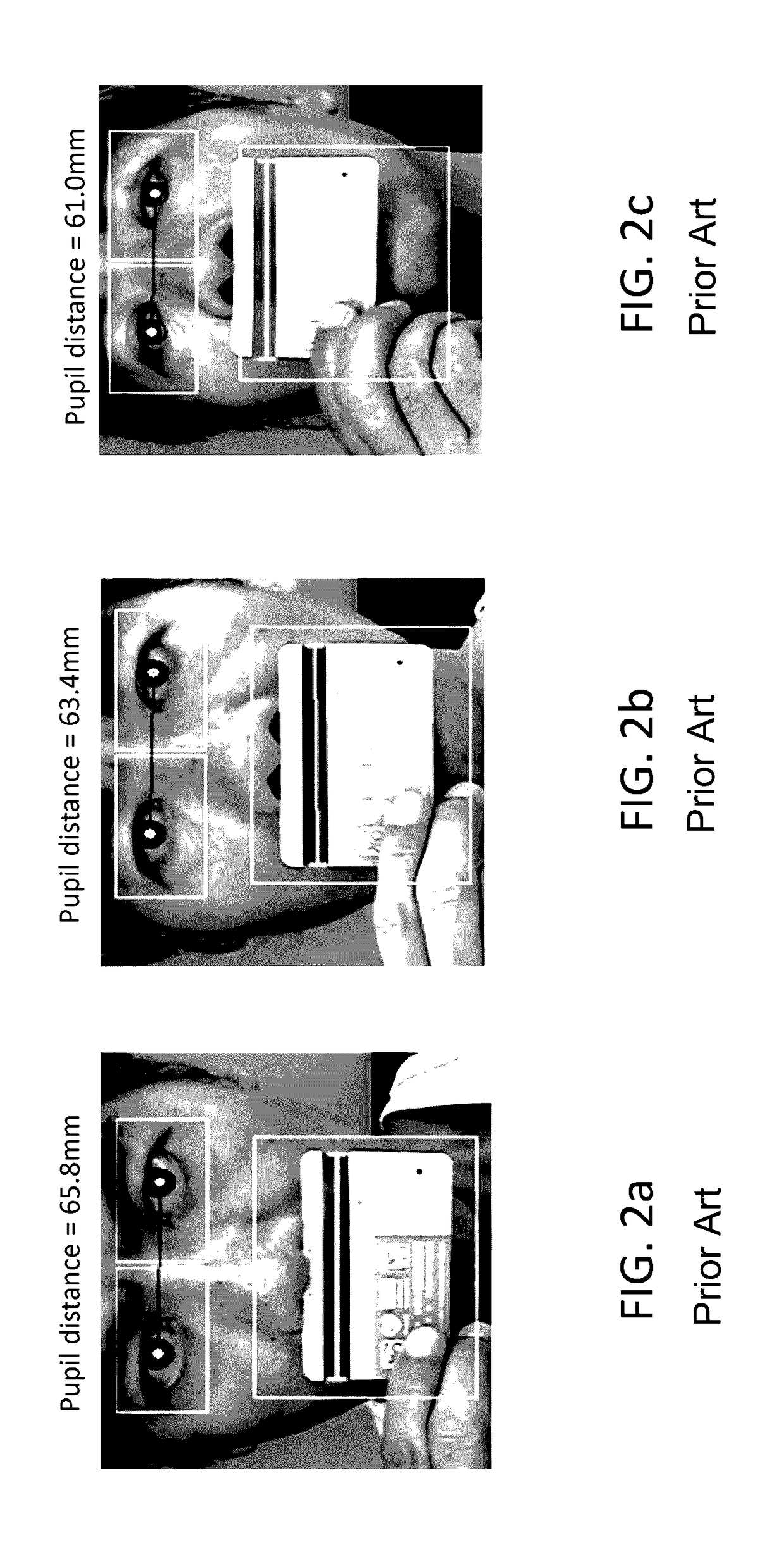
Therefore, even with the pupil distance being measured at the same measurement distance from the camera, the unsatisfactory or inadequate measurement accuracy of the pupil distance caused by differences in various head postures can be seen or determined.
Therefore, it is evident that at different head pitch angles, the pupil distance measurement results being obtained between 61.0 mm to 65.8 mm, are therefore not very precise or consistent.
Therefore, even with the same head posture, the insufficient measurement accuracy of the pupil distance obtained by the traditional manual pupillary distance (PD) measurement process caused by differences in various measuring distances of the head can be seen.
Therefore, it is evident that at different measurement distances of the head from the camera, the pupil distance measurement results being obtained ranged between 61.4 mm to 64.3 mm, are therefore are not very precise or consistent.
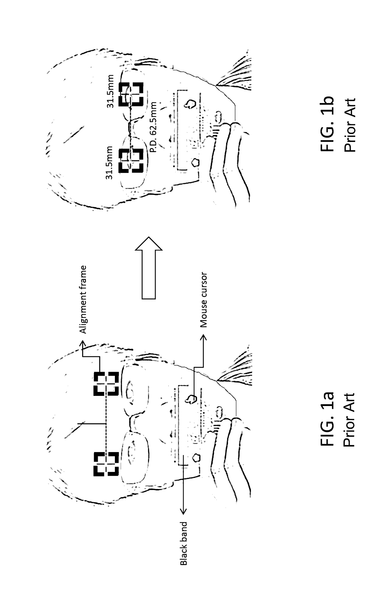
Thus, the drawbacks of the traditional manual pupillary distance measurement system as exemplified by examples and usage scenarios described above are as follow: (1) there lacks a proper constrain nor guidance from an UI design for the user to take photos with a front view and place the credit card on a face region properly; (2) there lacks a proper constrain or guidance from the UI design for the user to guide him to maintain a correct head posture and a correct measurement distance during the pupil distance measurement; (3) pupillary distance measurement requires of too many manual operation steps (such as in the form of mouse cursor moving and clicking) are needed to complete the pupil distance measurement process.
Therefore, the entire pupil distance measurement process is inconvenient and may be prone to produce pupil distance measurement errors.
In other words, disadvantages of conventional pupillary distance (PD) measuring system include for example, being more complicated to use, providing insufficient pupillary distance (PD) measurement accuracy, and achieving unsatisfactory overall user usage experience.

Method used


Image

  • Automatic pupillary distance measurement system and measuring method
  • Automatic pupillary distance measurement system and measuring method
  • Automatic pupillary distance measurement system and measuring method

Examples


first embodiment

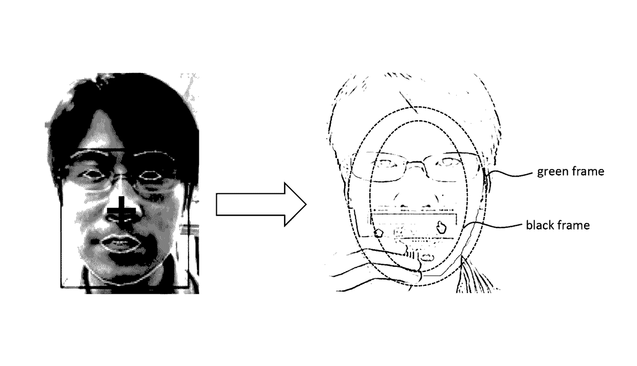
[0041]An automatic pupillary distance (PD) measurement method is described herein as follow. as shown in FIG. 5, an automatic pupillary distance (PD) measuring method using a camera and an user interface (UI), and performed using a processor of an electronic device, is described as follow in the following steps: In Step S1, A user is notified to move his or her head position to a center of a captured image, as shown in FIG. 4a. In Step S2, The user is notified to place a credit card inside the card window, as shown in FIG. 4b. In Step S3, the user is notified to move the head (moving the green-color dash-line frame illustrated as an enclosed dash line oval) forward / backward to fit within a target elliptical frame (black-colored dash line illustrated as an enclosed dash line oval) and maintain a correct head posture as shown in FIG. 4c. In Step S4, measurement of the pupil distance is started by the program, as shown in FIG. 4d. In Step S5, measurement of the pupil distance is compl...

second embodiment

[0043]Referring to a second embodiment, an automatic PD measurement method performed using a processor of an electronic device is shown from FIG. 6 to FIG. 8, which includes the following steps: In Step S10, the PD measuring method starts. In Step S15, the face image of a user is obtained from a camera. In Step S20, the facial features of the user are extracted. In Step S25, it is determine if the facial feature extraction is successful or not, and if so, proceed to Step S30; however if not, proceed to step S15. In Step S30, a head current center indicator (Cc) based on the facial feature extraction results obtained in Step S20 is shown / displayed. In Step S35, an elliptical frame and a target center indicator (Tc) of the entire face image is shown / displayed. In Step S40, a first distance (Ds) between the head current center indicator (Cc) and the target center indicator (Tc) is calculated, in which Ds=|Cc−Tc|. In Step S45, it is determined if the first distance (Ds) is below a thres...

third embodiment

[0044] a method of determining a target center and a target elliptical frame is provided and described in the following steps: First, referring to FIG. 9, a width and a height of the target elliptical frame is determined as follow: under a 640×480 resolution of image input, the size of the target elliptical frame is determined by experimental test (for example, using an iPhone 4s camera) at about one arm's length when holding the mobile device. The width is 208.0 pixels, and the height is 286.0 pixels. Second, the target center is determined. (a) In Step 1 as shown in FIG. 4, it is checked to see if the head is within a measurable range, just to set the target center as the image center, for example: (320, 240). (b) In Step 3 as shown in FIG. 4 also, the user is guided to move forward or backward. sy=30.0 pixels (center difference between facial tracking shape and target elliptical frame)

Center.x=curr_face_shape.cx;

Center.y=curr_face_shape.cy−sy;

where (curr_face_shape.cx, curr_face_...


PUM


Abstract

Method for automatically measuring pupillary distance includes extracting facial features of face image, a head current center indicator is shown / displayed based on facial feature extraction, elliptical frame and target center indicator are shown, a first distance between head current center indicator and target center indicator is calculated to see if below a threshold range, then allowing head current center indicator, elliptical frame and target center indicator to disappear. Card window based on facial tracking result is shown. Credit card band detection is performed to see if located within card window. Card window then disappear. Elliptical frame of moving head and target elliptical frame are shown. Elliptical frame of the moving head is aligned with the target elliptical frame and maintaining a correct head posture. If elliptical frame of moving head is aligned with target elliptical frame, then allow them to disappear from view, and performing a pupillary distance measurement.

Description

CROSS-REFERENCE TO RELATED APPLICATION[0001]This application is a non-provisional application claiming priority of U.S. provisional application No. 61 / 909,350, filed on Nov. 26, 2013. The entirety of the above-mentioned patent application is hereby incorporated by reference herein and made a part of this specification.BACKGROUND OF THE INVENTION[0002]1. Field of the Invention[0003]The present invention generally relates to a method for automatically measuring pupillary distance (PD), and more particularly, the present invention relates to an automatic pupillary distance (PD) measurement system and a PD measuring method having capability to automatically check to detect if a measured object moves into an adequate measuring position and automatically guide the user for obtaining a correct head posture for pupillary distance (PD) measurement.[0004]2. Description of the Related Art[0005]Nowadays, due to the improvements in the digital technologies with the increased demand in the curren...

Claims


Application Information

Patent Timeline
Patent Type & Authority Patents(United States)
IPC IPC(8): A61B3/11A61B3/14A61B3/00
CPCA61B3/111A61B3/0025A61B3/0033A61B3/0083A61B3/14
Inventor YE, ZHOUJENG, SHENG-WENLU, YING-KOLIU, SHIH WEI
Owner ULSEE
Learn More