Automatic pupillary distance measurement system and measuring method
a technology of automatic measurement and pupillary distance, applied in the field of automatic measurement of pupillary distance, can solve the problems of unsatisfactory or inadequate measurement accuracy of pupillary distance, poor overall user experience, and inconvenient use, so as to achieve more precise and robust pd measurement results, convenient and more accurate use, and satisfactory overall user experience.
- Summary
- Abstract
- Description
- Claims
- Application Information
AI Technical Summary
Benefits of technology
Problems solved by technology
Method used
Image
Examples
first embodiment
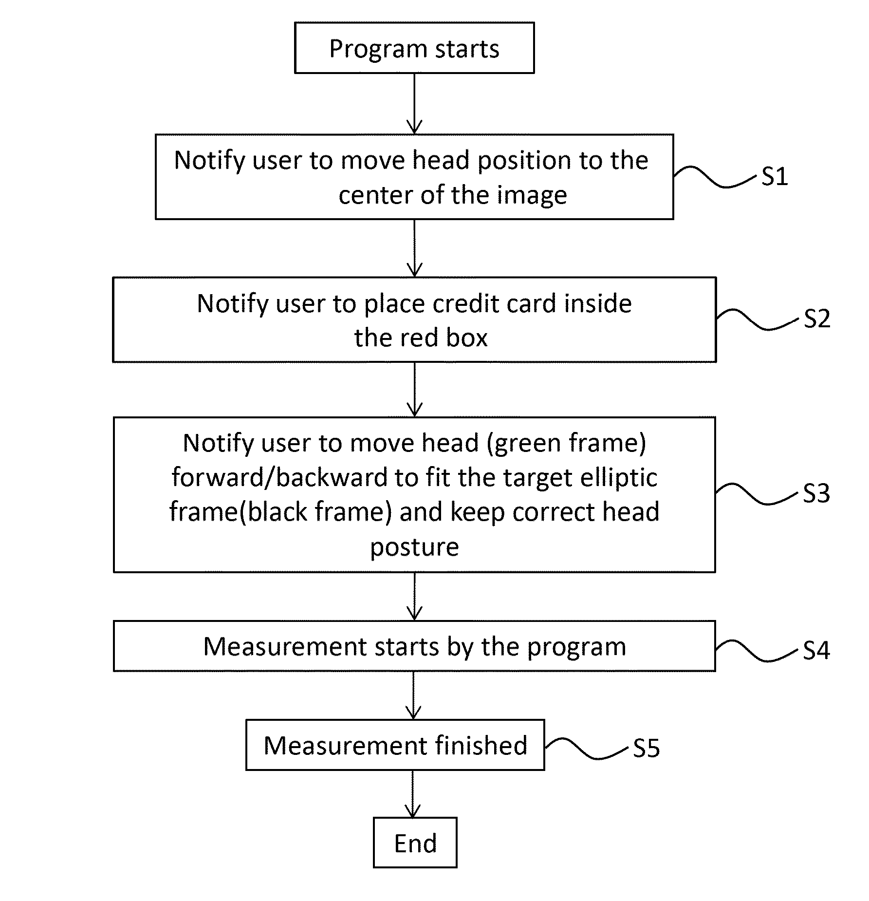
[0043]An automatic pupillary distance (PD) measurement method is described herein as follow. as shown in FIG. 5, an automatic papillary distance (PD) measuring method using a camera and an user interface (UI), and performed using a processor of an electronic device, is described as follow in the following steps: In Step S1, A user is notified to move his or her head position to a center of a captured image, as shown in FIG. 4a. In Step S2, The user is notified to place a credit card inside the card window, as shown in FIG. 4b. In Step S3, the user is notified to move the head (moving the green-color dash-line frame illustrated as an enclosed dash line oval) forward / backward to fit within a target elliptical frame (black-colored dash line illustrated as an enclosed dash line oval) and maintain a correct head posture as shown in FIG. 4c. In Step S4, measurement of the pupil distance is started by the program, as shown in FIG. 4d. In Step S5, measurement of the pupil distance is compl...
second embodiment
[0045]Referring to a second embodiment, an automatic PD measurement method performed using a processor of an electronic device is shown from FIG. 6 to FIG. 8, which includes the following steps: In Step S10, the PD measuring method starts. In Step S15, the face image of a user is obtained from a camera. In Step S20, the facial features of the user are extracted. In Step S25, it is determine if the facial feature extraction is successful or not, and if so, proceed to Step S30; however if not, proceed to step S15. In Step S30, a head current center indicator (Cc) based on the facial feature extraction results obtained in Step S20 is shown / displayed. In Step S35, an elliptical frame and a target center indicator (Tc) of the entire face image is shown / displayed. In Step S40, a first distance (Ds) between the head current center indicator (Cc) and the target center indicator (Tc) is calculated, in which Ds=|Cc−Tc|. In Step S45, it is determined if the first distance (Ds) is below a thres...
third embodiment
[0046] a method of determining a target center and a target elliptical frame is provided and described in the following steps: First, referring to FIG. 9, a width and a height of the target elliptical frame is determined as follow: under a 640×480 resolution of image input, the size of the target elliptical frame is determined by experimental test (for example, using an iPhone 4s camera) at about one arm's length when holding the mobile device. The width is 208.0 pixels, and the height is 286.0 pixels. Second, the target center is determined. (a) In Step 1 as shown in FIG. 4, it is checked to see if the head is within a measurable range, just to set the target center as the image center, for example: (320, 240). (b) In Step 3 as shown in FIG. 4 also, the user is guided to move forward or backward. sy=30.0 pixels (center difference between facial tracking shape and target elliptical frame)[0047]Center.x=curr_face_shape.cx;[0048]Center.y=curr_face_shape.cy−sy;[0049]where (curr_f ace_s...
PUM
 Abstract
Description
Claims
Application Information
 - R&D
- Intellectual Property
- Life Sciences
- Materials
- Tech Scout
- Unparalleled Data Quality
- Higher Quality Content
- 60% Fewer Hallucinations
Browse by: Latest US Patents, China's latest patents, Technical Efficacy Thesaurus, Application Domain, Technology Topic, Popular Technical Reports.
© 2025 PatSnap. All rights reserved.Legal|Privacy policy|Modern Slavery Act Transparency Statement|Sitemap|About US| Contact US: help@patsnap.com


