Microstructured reconfigurable composite material

a composite material and microstructure technology, applied in the field of composite materials, can solve the problems of affecting the efficiency of airframe design, and limiting the degree of optimization that can be achieved, so as to achieve highly segregated in-plane and out-of-plane stiffness properties, and high control of deformation and stiffness properties

Active Publication Date: 2017-05-09
HRL LAB
View PDF37 Cites 5 Cited by
  • Summary
  • Abstract
  • Description
  • Claims
  • Application Information

AI Technical Summary

Benefits of technology

[0012]According to an embodiment of the present invention, a microstructured composite material with controlled deformation is provided. The microstructured composite material includes a matrix material and at least three reinforcement layers embedded in the matrix material. The at least three reinforcement layers are embedded in the matrix material, and each of the at least three reinforcement layers includes a plurality of platelets arranged along a plane of the matrix material. A plurality of connecting members interconnect the plurality of platelets along the plane of the matrix material. Means is provided for mechanically coupling stress between adjacent layers of the at least three reinforcement layers to mitigate out-of-plane deformation of the matrix material while allowing deformation of the matrix material along the plane.
[0018]According to an embodiment of the present invention, a microstructured composite material with controlled deformation includes a matrix material and at least two reinforcement layers embedded in the matrix material. Each of the at least two reinforcement layers includes a plurality of support members. The support members of each layer of the at least two reinforcement layers extend substantially in parallel along a plane of the matrix material. The support members of a layer of the at least two reinforcement layers cross the support members of an adjacent layer of the at least two reinforcement layers. A plurality of connecting members interconnect the support members of adjacent layers of the at least two reinforcement layers at crossings between the support members. Two support members of the plurality of support members are pivotably interconnected by a corresponding one of the plurality of connecting members to mitigate translation between the two support members while allowing rotations between the two support members along the plane.
[0022]According to an embodiment of the present invention, a microstructured composite material with controlled deformation includes a matrix material and at least two reinforcement layers embedded in the matrix material. Each of the at least two reinforcement layers includes at least two platelets arranged along a plane of the matrix material. A first connecting member extends along the plane and interconnects two of the at least two platelets of a first layer of the at least two reinforcement layers. A second connecting member extends along the plane and interconnects two of the at least two platelets of a second layer of the at least two reinforcement layers. The second layer is adjacent to the first layer. The second connecting member crosses and interlocks with the first connecting member to mitigate translation between the first connecting member and the second connecting member while allowing rotation between the first connecting member and the second connecting member along the plane.

Problems solved by technology

However, fixed geometry structural elements limit the degree of optimization that can be achieved over the range of operating conditions.
Prior approaches to achieve a reconfigurable or morphing structure such as a morphing airplane wing rely on designs that are relatively mass-inefficient as compared to conventional airframe design.
The inefficiency results from the need to use soft, flexible materials such as shape memory polymer matrix composites as the wing skin, forcing structural mass to be concentrated in the interior where it reduces stiffness of the whole structure, as compared to torsion box designs.
The principal challenges in using fibers for these applications are the inextensibility of the fibers, limiting the deformation primarily to bending, and the poor stability of the fiber in compression leading to microbuckling.

Method used


Image

  • Microstructured reconfigurable composite material
  • Microstructured reconfigurable composite material
  • Microstructured reconfigurable composite material

Examples


Embodiment Construction

[0043]Detailed descriptions will be made below in reference to certain exemplary embodiments according to the present invention. The drawings and descriptions are to be regarded as illustrative in nature and not restrictive.

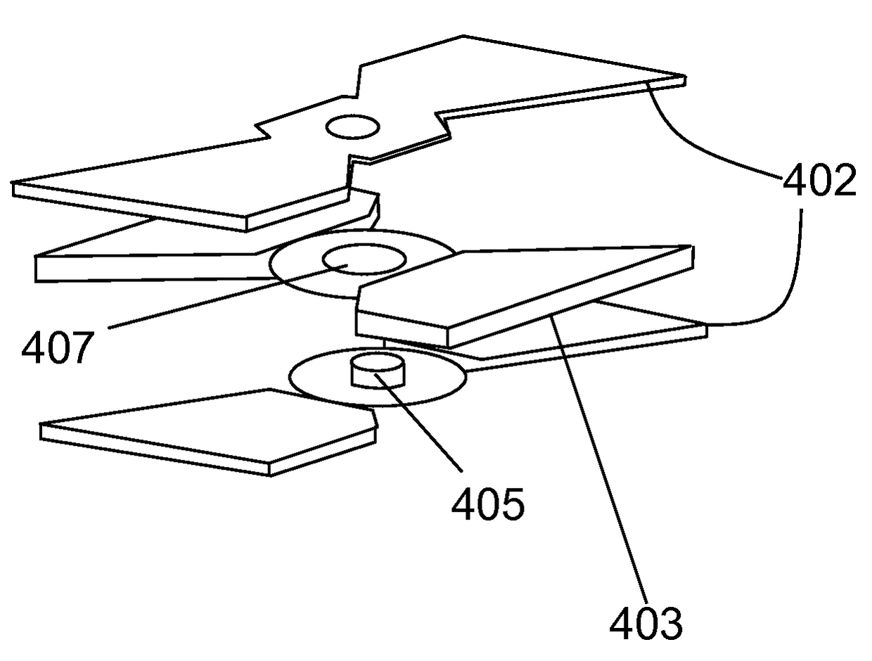
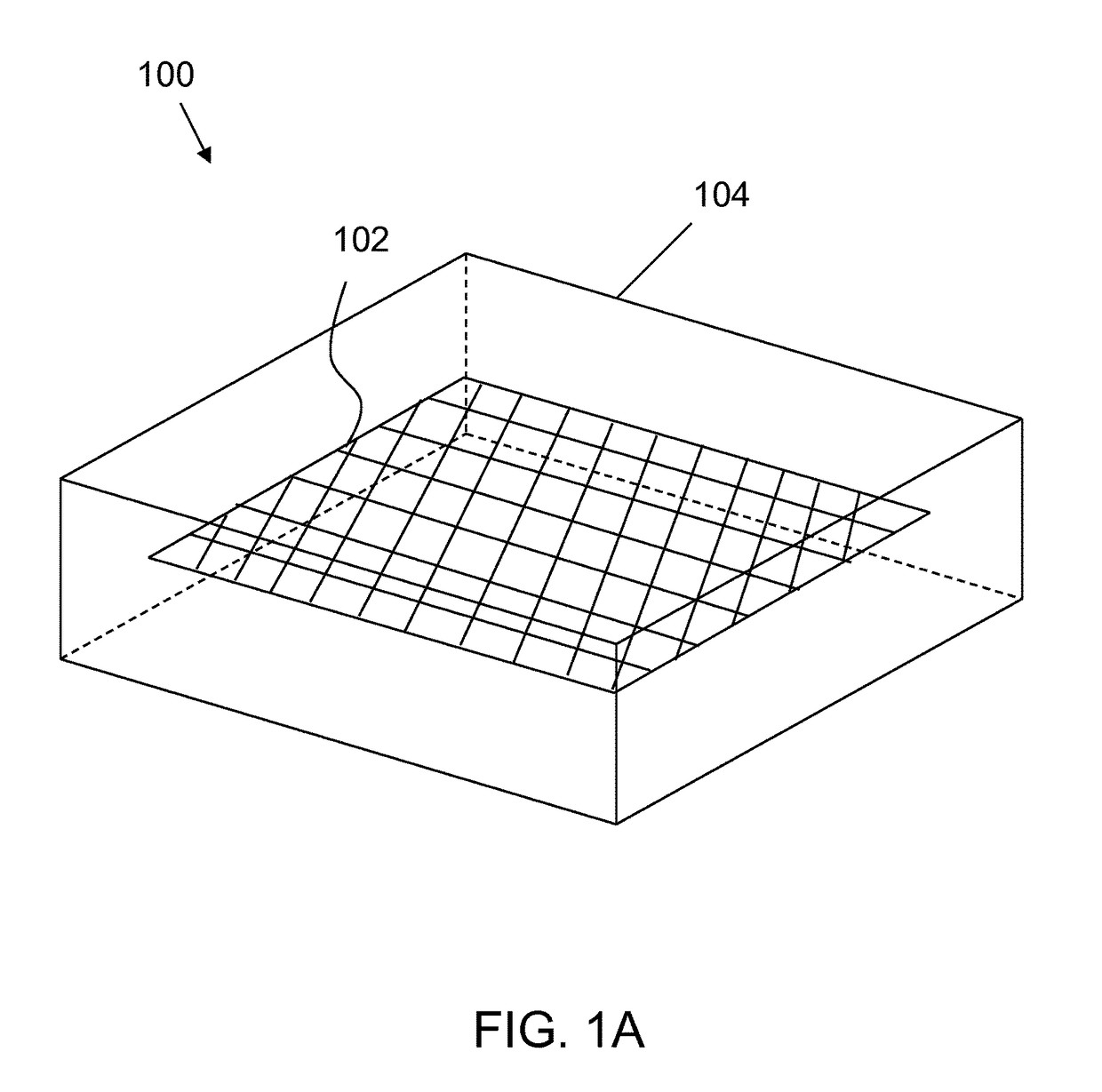
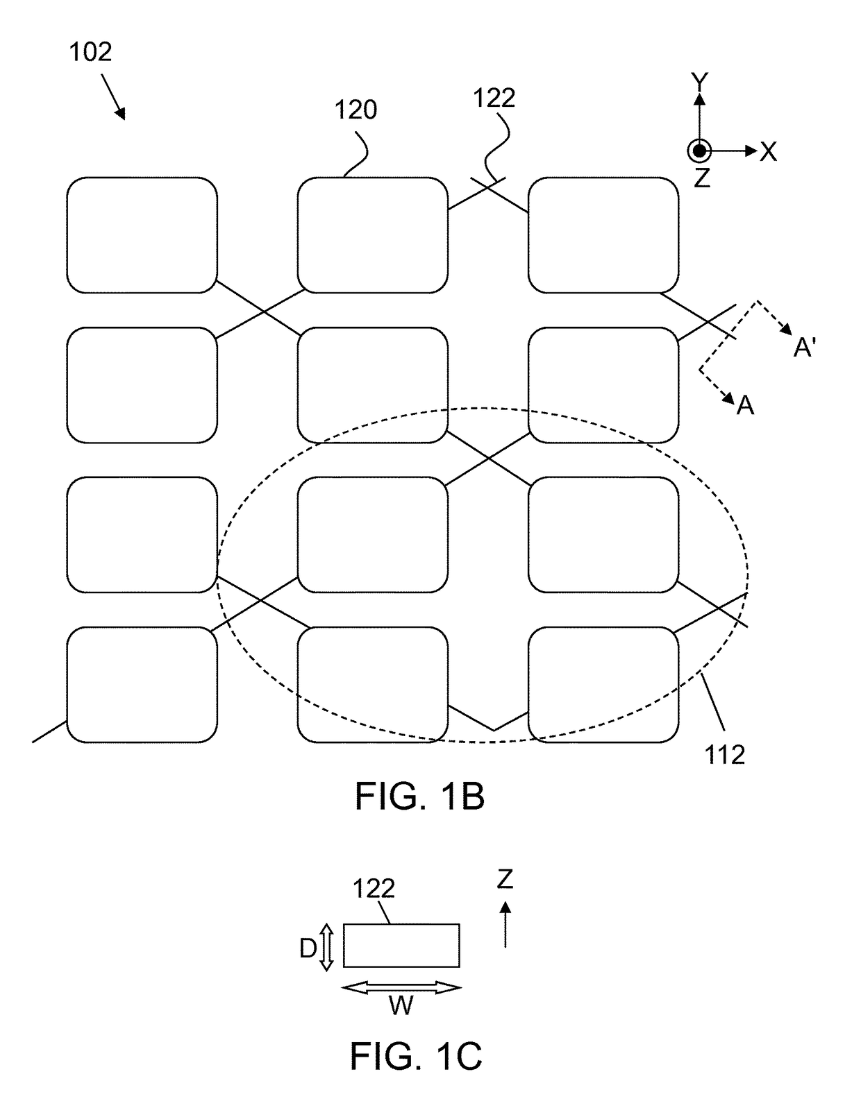
[0044]Embodiments of the present invention provide reconfigurable (or morphing) composite materials that provide highly controlled deformation and stiffness properties. The construction and operation of these materials with machine like properties macroscopically are enabled by utilizing machine like microstructures included in the material. Microscopic three dimensional (3D) structures are included in the materials to control their deformation and stiffness properties. Exemplary microscopic 3D features that may be included into the composite materials include bearing, ball and pin joints, and detents. The reconfigurable composite materials according to the embodiments of the present invention allow a range of new material properties to be enabled. These include ...


PUM

PropertyMeasurementUnit
aspect ratioaaaaaaaaaa

Abstract

A microstructured reconfigurable or morphing composite material with controlled anisotropic deformation properties. The composite material provides highly controlled deformation and stiffness properties. Microscopic three dimensional structures are included in the composite material to control its deformation kinematics and stiffness properties. The composite material has highly segregated in-plane and out-of-plane stiffness properties.

Description

CROSS-REFERENCE TO RELATED APPLICATION(S)[0001]This application is a divisional of U.S. patent application Ser. No. 12 / 354,662, filed on Jan. 15, 2009, which in turn is a continuation-in-part of U.S. patent application Ser. No. 12 / 212,469, filed on Sep. 17, 2008, issued as U.S. Pat. No. 8,409,691 on Apr. 2, 2013, which claims priority and benefit of U.S. Provisional Application No. 60 / 973,004, filed on Sep. 17, 2007, and is also related to U.S. patent application Ser. No. 11 / 193,148, filed on Jul. 29, 2005, issued as U.S. Pat. No. 7,550,189 on Jun. 23, 2009. The entire contents of all of the applications set forth above are incorporated herein by reference.STATEMENT REGARDING FEDERALLY SPONSORED RESEARCH OR DEVELOPMENT[0002]This invention was made with U.S. Government support under Contract No. FA8650-06-C-5059 awarded by the Air Force Research Laboratory. The U.S. Government has certain rights to this invention.BACKGROUND[0003]1. Field of the Invention[0004]The present invention is...

Claims


Application Information

Patent Timeline
Patent Type & Authority Patents(United States)
IPC IPC(8): B32B3/14
CPCB32B3/14B32B2260/046B32B2307/544B32B5/028B32B2260/023B32B2605/00Y10T428/24628B32B2260/048B32B2262/00B32B2307/546B32B2307/706B32B38/10B32B3/08Y10T428/29B32B2260/00B32B2305/07B32B2305/08B32B2605/18B32B2307/50
Inventor MCKNIGHT, GEOFFREY P.HENRY, CHRISTOPHER PAULHERRERA, GUILLERMO
Owner HRL LAB
Why Eureka
Try Eureka