Manufacturing method of electronic device, electronic device, electronic apparatus, moving object, and lid body

a manufacturing method and electronic technology, applied in the direction of electrical apparatus casings/cabinets/drawers, instruments, semiconductor/solid-state device details, etc., can solve the problems of deterioration of electronic components, suppress the characteristic degradation of electronic components, and achieve the effect of reducing the amount of molten substances, and facilitating melting

Active Publication Date: 2017-05-09
COLUMBIA PEAK VENTURES LLC
View PDF31 Cites 0 Cited by
  • Summary
  • Abstract
  • Description
  • Claims
  • Application Information

AI Technical Summary

Benefits of technology

[0009]According to the manufacturing method of an electronic device, the groove of the lid body is provided to have a smaller opening area on the inner space side (central side) than the opening area on the outer circumferential side. Accordingly, the opening of the groove on the inner space side is narrow, therefore, when welding is performed, scattered molten substance of the lid body (also referred to as weld splash or dross) is likely to be attached to an inner wall of the groove, and thus it is possible to reduce an amount of the molten substance that enters the inner space. Accordingly, it is possible to suppress characteristic degradation in the electronic component due to the attachment of the scattered substance to the electronic component. In addition, in the second welding in which the groove is closed, since the opening area of the groove is great, it is possible to easily perform melting because the remaining volume of the lid body at the melting portion is small. Therefore, it is possible to realize stable melting and to achieve reduction of the scattered substance. In addition, the welding of the base and the lid body in the first welding can be performed with a direct welding method for the base and the lid body, or a welding method in which another joining member, such as a metal member, is provided between the base and the lid body, and the welding is performed through the joining member.Application Example 2
[0011]In the configuration described above, the inner space communicates with the outside through the groove provided on the lid body, and thus it is possible to easily perform pressure reduction of the inner space or to easily make the inner space an inert gas atmosphere. The gas in the inner space is expelled between the first welding and the second welding, and the groove at the communicating portion is closed by welding. Accordingly, it is possible to seal the inner space in which the pressure reduction is performed or which has the inert gas atmosphere. Therefore, it is possible to perform sealing after the gas produced during welding of the lid body is removed from the inside of the package, and thus it is possible to realize high-quality air-tight sealing with a simplified manufacturing process.Application Example 3
[0016]When the lid body having a configuration described in any one of Application Examples 3 to 6 is used, it is possible to have the smaller opening area of the groove provided on the lid body on the inner space side (center side) rather than the opening area of the groove on the outer circumferential side. Accordingly, when welding is performed to close the groove, the scattered molten substance of the lid body is likely to be attached to the inner wall of the groove, and thus it is possible to reduce the amount of the molten substance that enters the inner space. In addition, in the second welding in which the groove is closed, since the opening area of the groove is great, it is possible to easily perform melting because the remaining volume of the lid body is small. Therefore, it is possible to realize stable melting and to achieve reduction of the scattered substance.Application Example 7
[0024]According to the lid body, the opening area of the groove on the inner space side is narrower (smaller) than on the outer circumferential side of the lid body. Therefore, when welding with the base is performed, the scattered molten substance of the lid body is likely to be attached to the inner wall of the groove, and thus it is possible to reduce the amount of the molten substance that enters the inner space. Accordingly, it is possible to suppress characteristic degradation in the electronic component due to the attachment of the scattered substance to the electronic component that is accommodated in the inner space. In addition, during the welding in which the groove is closed, since the opening area of the groove is great, it is possible to easily perform melting because the remaining volume of the lid body is small. Therefore, it is possible to realize stable melting and to achieve reduction of the scattered substance.

Problems solved by technology

However, in the joining method described above, there is a concern that, when the second melting of the metal brazing material is performed at the notched portion such that the lid body and the package are sealed, the molten metal brazing material scatters from the notched portion to an inner space, and is attached to an electronic component that is accommodated in the inner space, and thus characteristics of the electronic component deteriorate.

Method used


Image

  • Manufacturing method of electronic device, electronic device, electronic apparatus, moving object, and lid body
  • Manufacturing method of electronic device, electronic device, electronic apparatus, moving object, and lid body
  • Manufacturing method of electronic device, electronic device, electronic apparatus, moving object, and lid body

Examples


first embodiment

of Electronic Device

[0043]First, an embodiment of a vibrator is described as a first embodiment of an electronic device that is manufactured, to which the manufacturing method of an electronic device according to the invention is applied.

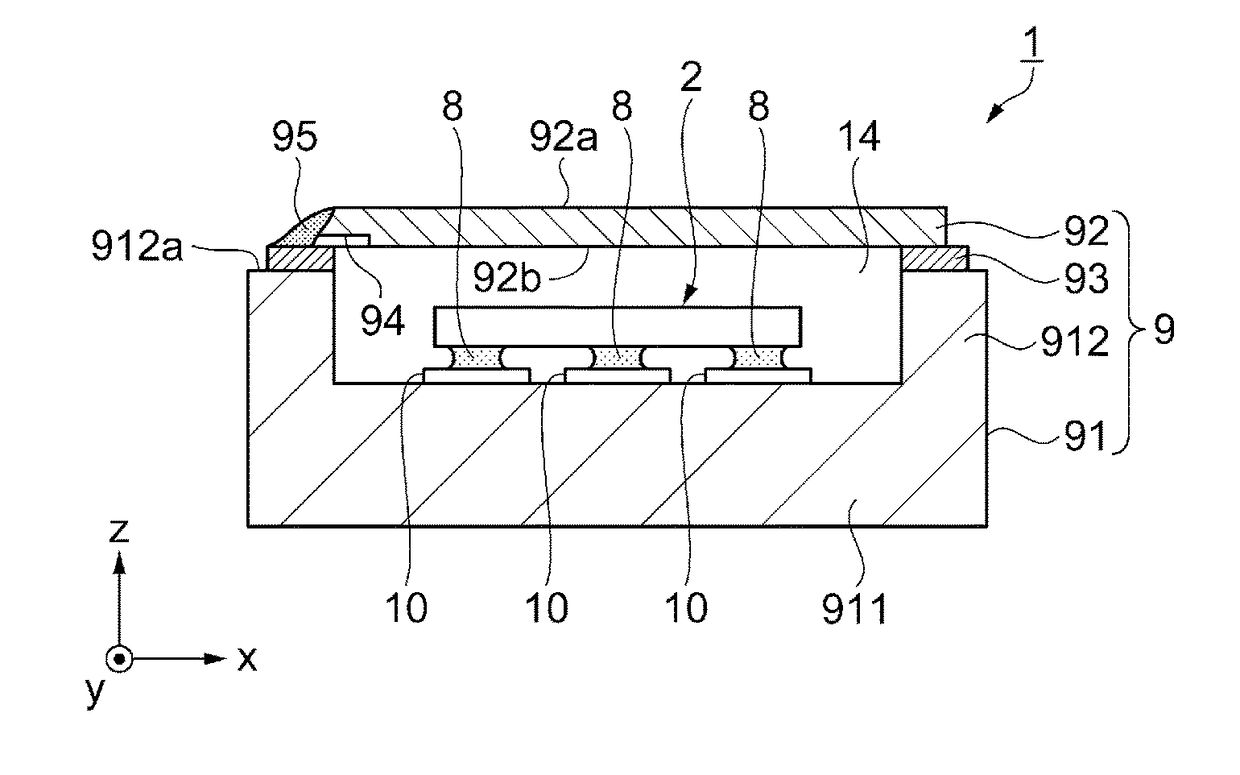
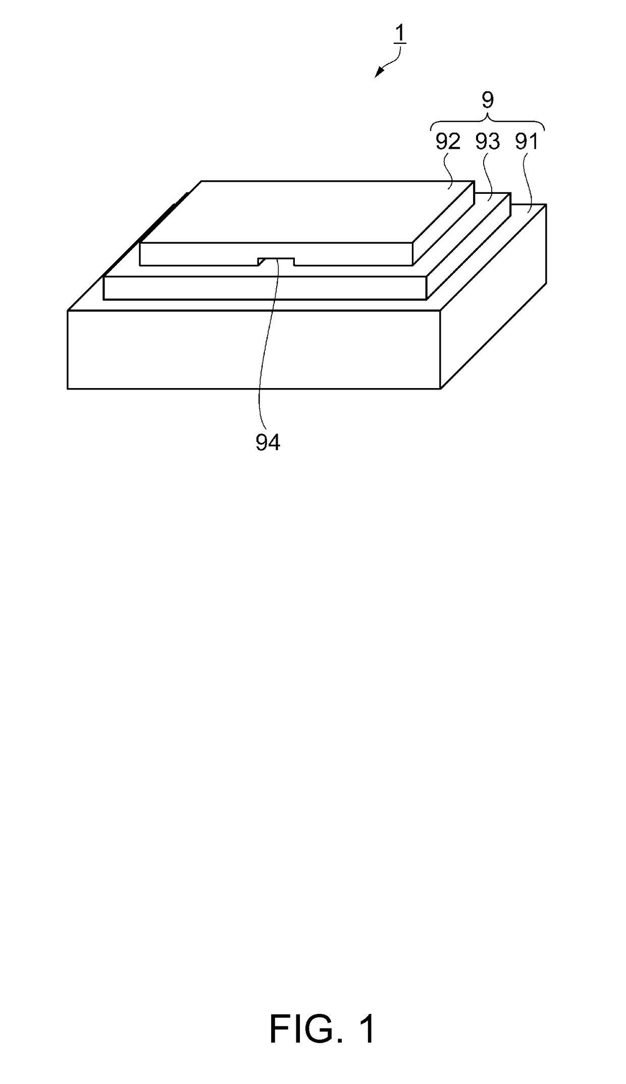
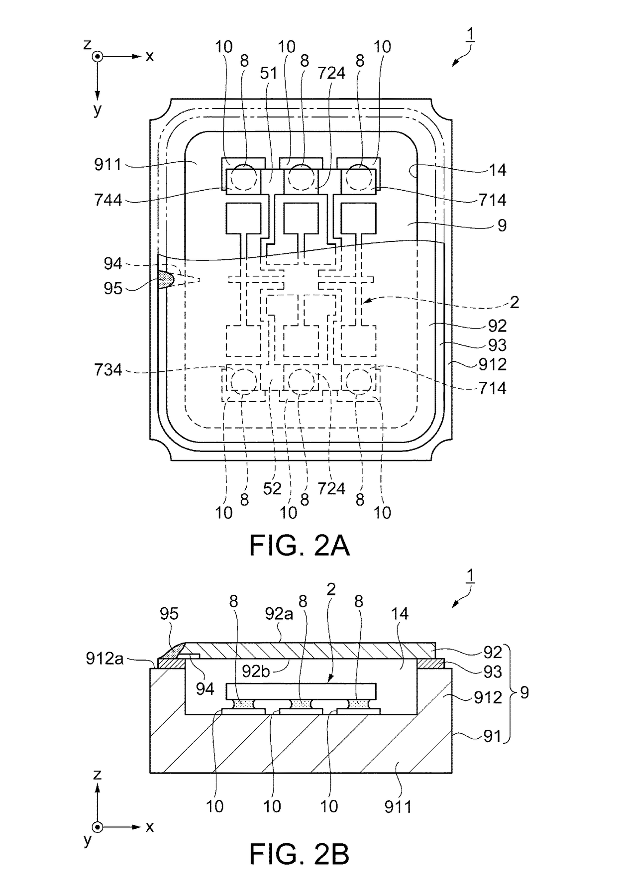
[0044]FIG. 1 is a perspective view schematically illustrating the vibrator as the first embodiment of the electronic device according to the invention. FIGS. 2A and 2B are views schematically illustrating the vibrator as the first embodiment of the electronic device according to the invention. FIG. 2A is a plan view, and FIG. 2B is a front cross-sectional view. FIG. 3 is a plan view illustrating a gyro element as an electronic component that is included in the vibrator illustrated in FIGS. 2A and 2B. From here on, as illustrated in FIGS. 2A and 2B, three axes orthogonal to each other are an x axis, a y axis, and a z axis, and the z axis matches the thickness direction of the vibrator. In addition, a direction parallel to the x axis is referred to as...

modification example 1

of Groove in Joining Process

[0083]According to the first embodiment described above, as illustrated in FIG. 6A, when the lid 92 is mounted on the seam ring 93 and joined to the base 91, the groove 94 extends so as to enter the inner space 14 from the outer circumferential surface 92c of the lid 92, and thus the communicating portion in which the inner space 14 and the outside of the base 91 communicate with each other through the groove 94 is formed. However, the groove 94 may not extend to the inner space 14. That is, the groove 94 may be present in a region between the inner circumferential surface 93a of the seam ring 93 and the outer circumferential surface 92c of the lid 92 without overlapping the inner space 14 in a plan view. In this case, the groove 94 does not communicate with the inner space 14. However, on a surface of the lid 92 (rear surface 92b) on a side where the groove 94 is provided, a region adjacent to the groove 94, that is, a region adjacent to the inner space ...

modification example 2

of Groove in Joining Process

[0084]In addition, the groove 94 may have a shape as illustrated in FIGS. 7A and 7B. FIGS. 7A and 7B are plan views illustrating Modification Example 2 of the groove. FIG. 7A is a plan view illustrating the groove before sealing, and FIG. 7B is a plan view illustrating the groove after sealing. As illustrated in FIGS. 7A and 7B, the groove 94 of Modification Example 2 has a width that is decreased in a stepwise manner toward the inner space 14, in a plan view. To be more specific, in the groove 94 of Modification Example 2, a first groove that extends from the one end 94a of the groove 94 that is opened by the width L1 to the inner space 14 and a second groove that extends from the other end 94b on the inner space 14 side of the groove 94 and has the width L3 smaller (narrower) than the width L1 are connected at a position 94d on the seam ring 93, on the outer circumferential surface 92c side of the lid 92. That is, the opening 94c on the inner space 14 s...


PUM

PropertyMeasurementUnit
width L1aaaaaaaaaa
width L1aaaaaaaaaa
depth L2aaaaaaaaaa

Abstract

A manufacturing method of an electronic device, that accommodates a gyro element as an electronic component in an inner space formed by a base and a lid as a lid body, includes: preparing the lid in which a groove is provided on a surface which is welded with the base, and an opening area of the groove on the inner space side which is smaller than an opening area on the outer periphery side of the lid; welding, first, the base and the lid at a portion excluding an unwelded portion that includes at least apart of the groove, of a planned welding portion of the base and the lid; and welding, second, the base and the lid at the unwelded portion such that the groove is closed.

Description

BACKGROUND[0001]1. Technical Field[0002]The present invention relates to a manufacturing method of an electronic device, an electronic device, an electronic apparatus, a moving object, and a lid body.[0003]2. Related Art[0004]Recently, portable electronic apparatuses are widely used, and thus reduction in size, weight, and cost of the electronic apparatuses is highly desired. Therefore, reduction in size and cost of an electronic component used in the electronic apparatus is highly required, while accurate performance is maintained. Particularly, in a vibration device that accommodates a vibration element in a package, a space to accommodate the vibration element needs to be maintained to be air-tight, which causes vibration characteristics to be maintained. Therefore, various sealing techniques are proposed.[0005]For example, a manufacturing method of a miniaturized quartz crystal vibrator disclosed in JP-A-1-151813 includes forming a notch on a package surface on which a lid (lid ...

Claims


Application Information

Patent Timeline
Patent Type & Authority Patents(United States)
IPC IPC(8): B23K31/02G01C19/5769H05K5/06H01L23/10G01C19/574B23K101/12
CPCG01C19/5769G01C19/574H01L23/10H05K5/066B23K2201/12B23K2101/12H01L2224/16225H01L2224/73204H01L2924/16195
Inventor AOKI, SHINYAKAWAUCHI, OSAMUMATSUZAWA, JUICHIROMIKAMI, MASARU
Owner COLUMBIA PEAK VENTURES LLC
Why Eureka
Try Eureka