Control valve for a variable displacement compressor

a variable-discharge compressor and control valve technology, applied in the direction of positive-discharge liquid engines, liquid fuel engines, lighting and heating apparatus, etc., can solve the problem of relatively and prevent or suppress the occurrence of foreign material entanglement. , the effect of small clearance on the low-pressure sid

Active Publication Date: 2017-05-16
TGK
View PDF14 Cites 4 Cited by
  • Summary
  • Abstract
  • Description
  • Claims
  • Application Information

AI Technical Summary

Benefits of technology

[0012]In order to resolve the aforementioned problems, a control valve, for a variable displacement compressor, according to one embodiment of the present invention is a control valve for a variable displacement compressor for varying a discharging capacity of the variable displacement compressor by controlling a flow rate of refrigerant to be introduced from a discharge chamber to a crankcase of the compressor, and the control valve includes: a body having a discharge pressure chamber that communicates with the discharge chamber, a crank pressure chamber that communicates with the crankcase, a valve hole provided in a passage joining the discharge pressure chamber to the crank pressure chamber, and a guiding passage formed coaxially with the valve hole; an actuating rod slidably supported along the guiding passage, the actuating rod having a valve element configured to open and close a valve section such that the valve element touches and leaves the valve hole; a solenoid configured to apply a solenoidal force in an opening or closing direction of the valve section to the valve element via the actuating rod; and a seal section provided between the actuating rod and the guiding passage, the seal section containing a sealing member therein where the sealing member serves to restrict leakage of the refrigerant from a high pressure side to a low pressure side. The actuating rod and the guiding passage are configured such that a clearance, between the actuating rod and the guiding passage, which is at a higher-pressure side of the seal section is larger than a clearance therebetween which is at a lower-pressure side of the seal section and a clearance length in the axial direction on the higher-pressure side of the recessed groove is shorter than a clearance length in the axial direction on the lower-pressure side of the recessed groove.
[0013]By employing this embodiment, the sealing member is pressed in such a manner as to close a low-pressure—side clearance due to a pressure difference between a high-pressure side and a low-pressure side. As a result, the sealing property of a sliding portion of the actuating rod can be satisfactorily maintained. Also, the low-pressure-side clearance is relatively small. This can prevent the problem of an excessive sliding friction caused by the sealing member stuck in the low-pressure-side clearance. At the same time, the high-pressure-side clearance is relatively large; if foreign material enters from the high pressure side, the occurrence of the foreign material being entangled can be prevented or suppressed. As a result, the smooth operation of the actuating rod and eventually the valve element can be maintained.

Problems solved by technology

Also, the low-pressure-side clearance is relatively small.

Method used


Image

  • Control valve for a variable displacement compressor
  • Control valve for a variable displacement compressor
  • Control valve for a variable displacement compressor

Examples


first embodiment

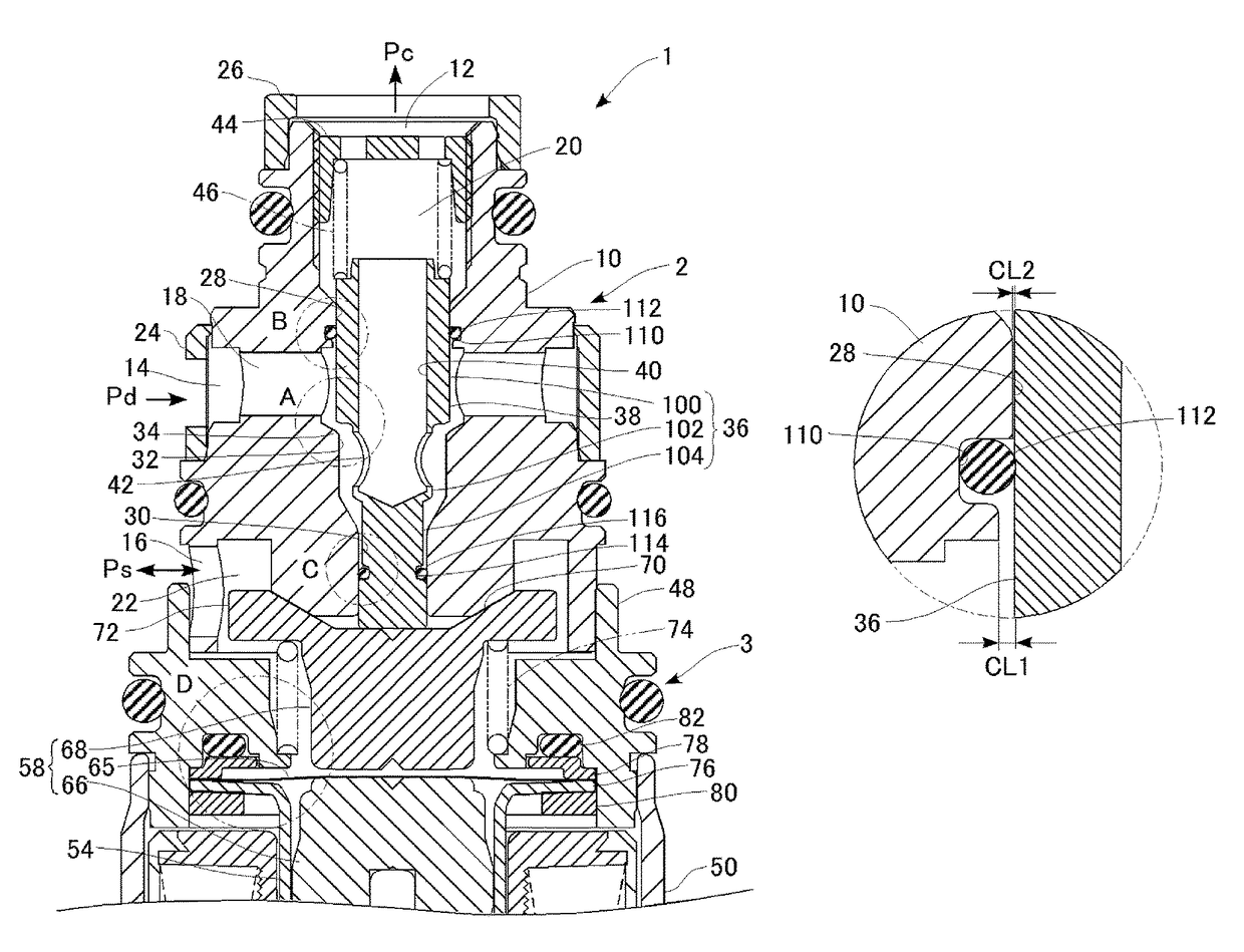
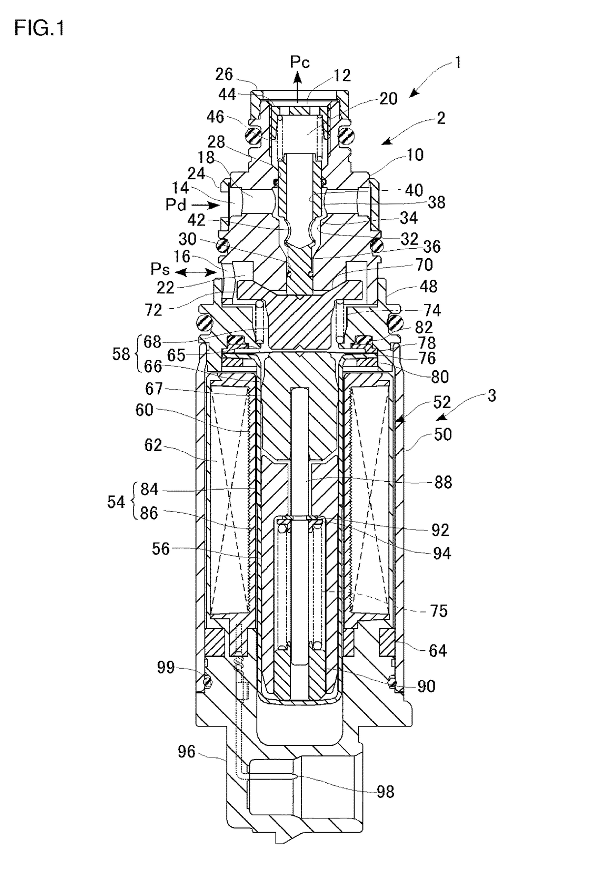
[0027]FIG. 1 is a cross-sectional view showing a structure of a control valve according to a first embodiment of the present invention.

[0028]A control valve 1 according to the present embodiment is constituted as a control valve for controlling a not-shown variable displacement compressor (hereinafter referred to simply as “compressor”) to be installed for a refrigeration cycle of an automotive air conditioner. This compressor discharges a high-temperature and high-pressure gas refrigerant produced by compressing a refrigerant flowing through the refrigeration cycle. The gas refrigerant is then condensed by a condenser (external heat-exchanger) and further adiabatically expanded by an expander so as to become a misty, low-temperature and low-pressure refrigerant. This low-temperature and low-pressure refrigerant is evaporated by an evaporator, and the evaporative latent heat cools the air of an interior of a vehicle. The refrigerant evaporated by the evaporator is again brought back...

second embodiment

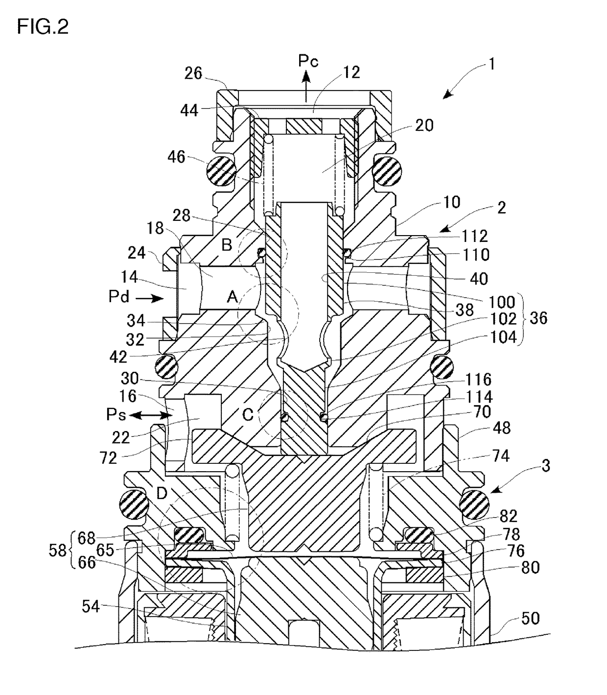
[0066]A description is now given of a second embodiment of the present invention. A control valve according to the second embodiment shares many common features with the first embodiment except for the structure and arrangement of a body and a valve driven member. Thus, the structural components of the second embodiment closely similar to those of the first embodiment are given the identical reference numerals and the description thereof is omitted as appropriate. FIG. 8 is a partially enlarged sectional view of an upper half the control valve according to the second embodiment of the present invention. FIGS. 9A and 9B each shows a seal structure of a sliding portion. FIG. 9A is an enlarged view of area marked with B in FIG. 8, and FIG. 9B is an enlarged view of area marked with C in FIG. 8. FIG. 10 shows an operational process of a control valve and shows a state where a bleed function of the control valve is performed. FIG. 8 shows a state where the control valve operates with the...


PUM


Abstract

A control valve according to an embodiment includes a body having a valve hole and a guiding passage formed coaxially with the valve hole, an actuating rod, slidably supported along the guiding passage, which is provided with a valve element, a solenoid for applying the solenoidal force in an opening or closing direction of a valve section to the valve element via the actuating rod, and a seal section, provided between the actuating rod and the guiding passage, which houses a sealing member for restricting the leakage of refrigerant from a high pressure side to a low pressure side. The actuating rod and the guiding passage are configured such that the clearance, between the actuating rod and the guiding passage, which is at a higher-pressure side of the seal section is larger than the clearance which is at a lower-pressure side of the seal section.

Description

CLAIM OF PRIORITY TO RELATED APPLICATION[0001]The present application is claiming priority of Japanese Patent Application No. 2012-097869, filed on Apr. 23, 2012, the content of which is incorporated herein by reference.BACKGROUND OF THE INVENTION[0002]1. Field of the Invention[0003]The present invention relates to a control valve suitable for controlling a discharging capacity of a variable displacement compressor.[0004]2. Description of the Related Art[0005]An automotive air conditioner generally includes a compressor, a condenser, an expander, an evaporator, and so forth. The compressor compresses a refrigerant flowing through a refrigerant cycle of the air conditioner and then discharges the thus compressed refrigerant as a higher-temperature and high-pressure gas refrigerant. The condenser condenses the gas refrigerant. The expander adiabatically expands the condensed liquid refrigerant so as to produce a low-temperature and low-pressure refrigerant. Then the evaporator evapora...

Claims


Application Information

Patent Timeline
Patent Type & Authority Patents(United States)
IPC IPC(8): F04B27/18F25B1/02F04B49/22F04B49/02F04B1/26F04B53/10
CPCF04B27/1804F04B1/26F04B27/18F04B49/02F04B49/22F25B1/02F04B53/1082F04B2027/185F04B2027/1813F04B2027/1827F04B2027/1845Y10T137/794Y10T137/85978F04B27/14F04B53/00
Inventor SAKAKIBARA, HIDEKAZUKOBAYASHI, TAKASHIMIYAZAKI, MICHIYOSHITAMOTSU, KOTAKASHIMAZAKI, SATOSHI
Owner TGK
Why Eureka
Try Eureka