
DC side fault isolator for high voltage DC convertors

a dc converter and side fault technology, applied in the direction of power conversion systems, emergency protective circuit arrangements, electrical equipment, etc., can solve the problems of low surge current withstand capability, general cost and relatively high conduction loss, and damage to diodes,

Inactive Publication Date: 2017-05-16
QATOR FOUND FOR EDUCATION SCI & COMMUNITY DEV +1
View PDF11 Cites 3 Cited by
  • Summary
  • Abstract
  • Description
  • Claims
  • Application Information

AI Technical Summary

Benefits of technology

The patent describes a device that prevents high voltage direct current (HVDC) converters from being affected by direct current faults. The device uses double thyristor switches to isolate the converter from external power grids during these faults. This prevents damage and ensures the continued safe operation of the converter. The patent also mentions that the device can be used in two-level voltage-source converters or half-bridge modular multilevel converters, depending on the needs of the converter.

Problems solved by technology

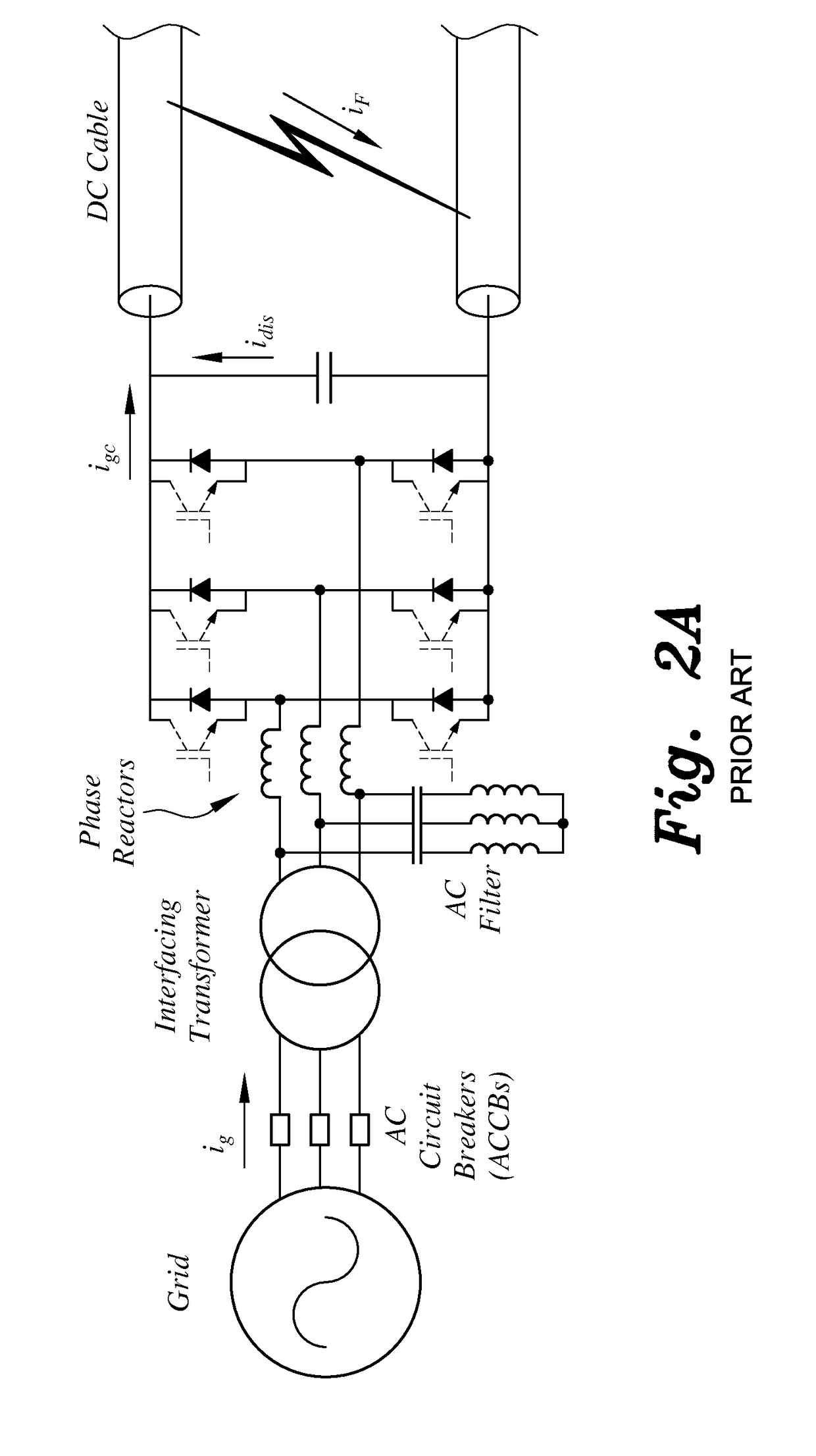
Unfortunately, the VSC and half-bridge MMC are defenseless against DC side faults since their free-wheeling diodes function as an uncontrolled rectifier bridge and feed the DC fault, even if the semiconductor devices are turned off.
As a result, the diodes can be damaged due to the high fault current.
A solid state DC circuit breaker can be used to overcome the DC side problems in HVDC converters, however its main drawbacks are generally cost and relatively high conduction losses.
AC circuit breakers (ACCBs) can be used to achieve the required DC protection, but the free-wheeling diodes used with IGBTs are fast recovery diodes characterized by low surge current withstand capability.
Thus, there can be a risk in depending on ACCB protection alone, since the semiconductor devices can be damaged due to high fault currents.
However, the main drawbacks of this method generally are: both thyristors have to withstand high dv / dt during normal operation (high dv / dt can produce capacitive displacement current in the device, which can cause undesirable turn on); a snubber circuit is also typically essential to prevent damage due to overvoltage spikes and dv / dt; the free-wheeling diodes are still sharing the fault current with the thyristors; and the complexity of implementing an embedded double thyristor switch in each MMC sub-module.

Method used


Image

  • DC side fault isolator for high voltage DC convertors
  • DC side fault isolator for high voltage DC convertors
  • DC side fault isolator for high voltage DC convertors

Examples


Embodiment Construction

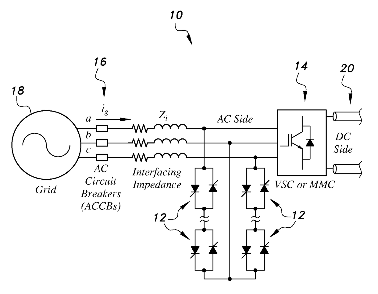
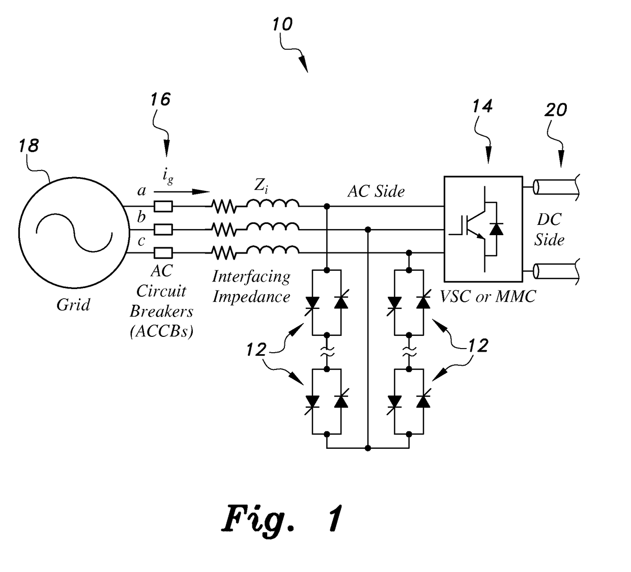
[0046]As shown in FIG. 1, in the DC side fault isolator for high voltage DC (HVDC) converters 10, double thyristor switches 12 are combined and connected across the AC output terminals of a HVDC converter 14 (which can be either a VSC or MMC). Normally, the thyristors 12 are turned off. When a DC side fault is initiated, the thyrsistors 12 are turned on to segregate the HVDC converter from the AC side. From fault inception until the tripping of the ACCBs 16, the DC side fault isolator for HVDC converters 10 can provide the needed protection for the semiconductor devices of the HVDC converter 14 as well as complete segregation between the AC grid 18 and the DC side 20, i.e., the grid current contribution is eliminated or substantially eliminated.

[0047]In the case of the conventional two-level VSC, the equivalent impedance seen by the grid 18 during the DC side fault before and after firing the thyristors 12 is the same, which is equal to the impedance of the interfacing impedance (4)...


PUM


Abstract

The direct current (DC) side fault isolator for high voltage direct current (HVDC) converters (10) includes a first set of double thyristor switches (12) connected across the line-to-line voltage terminals between first and second phases of alternating current (AC) terminals of a HVDC converter (14), and a second set of double thyristor switches (12) connected across the line-to-line voltage between the second phase and a third phase of the AC terminals of the HVDC converter (14). In use, the first and second sets of double thyristor switches (12) separate the HVDC converter (10) from an external power grid (18) during direct current (DC) side faults by turning on these thyristors (12).

Description

TECHNICAL FIELD[0001]The present invention relates to high voltage direct current (HVDC) converters, and particularly to a DC side fault isolator for HVDC converters for separating the HVDC converter from an external power grid during direct current side faults.BACKGROUND ART[0002]A high voltage direct current (HVDC) converter converts electric power from high voltage alternating current (AC) to high voltage direct current, or vice-versa. HVDC is used as an alternative to AC for transmitting electrical energy over long distances or between AC power systems of different frequencies. A complete converter station can contain several such converters in series and / or parallel (multi-module HVDC converters).[0003]HVDC converters are divided into two main categories: line-commutated converters and forced-commutated voltage-sourced converters. Line-commutated converters use on-controlled and off-uncontrolled switches; i.e., thyristors. Forced-commutated voltage-source converters (VSCs) use ...

Claims


Application Information

Patent Timeline
Patent Type & Authority Patents(United States)
IPC IPC(8): H02M7/155
CPCH02M7/1552H02H7/1257H02M1/32H02M7/4835
Inventor ELSEROUGI, AHMEDABDEL-KHALIK, AYMANMASSOUD, AHMEDAHMED, SHEHAB
Owner QATOR FOUND FOR EDUCATION SCI & COMMUNITY DEV
Learn More