Check patentability & draft patents in minutes with Patsnap Eureka AI!

Light emitting module and display device

a technology of light emitting modules and display devices, applied in the direction of optical light guides, instruments, optics, etc., can solve the problems of reducing the overall quality of the front light module, and the light beam entering the light guide plate is not uniform, so as to achieve uniform color and brightness

Active Publication Date: 2017-05-30
E INK HLDG INC
View PDF14 Cites 0 Cited by
  • Summary
  • Abstract
  • Description
  • Claims
  • Application Information

AI Technical Summary

Benefits of technology

The solution provides a uniform light beam with enhanced color and brightness, improving the light source quality and enabling a superior display image in display devices.

Problems solved by technology

Thus, due to the high directionality and the needs to convert with the phosphors, the most preferable light is usually received from a position just in front of the light emitting surface of the white light emitting diode, and peripheral light of the light emitting surface usually has a lower color temperature, which makes the light beam entering the light guide plate not uniform, thereby reducing an overall quality of the front light module.

Method used


Image

  • Light emitting module and display device
  • Light emitting module and display device
  • Light emitting module and display device

Examples


Embodiment Construction

[0024]Reference will now be made in detail to the present preferred embodiments of the invention, examples of which are illustrated in the accompanying drawings. Wherever possible, the same reference numbers are used in the drawings and the description to refer to the same or like parts.

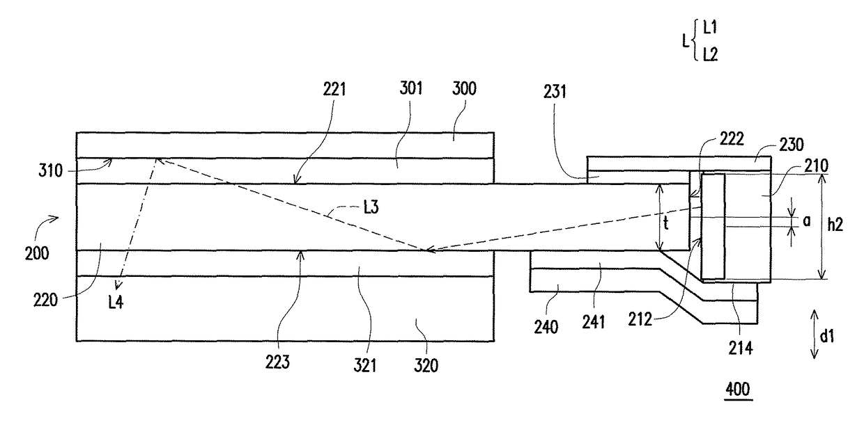
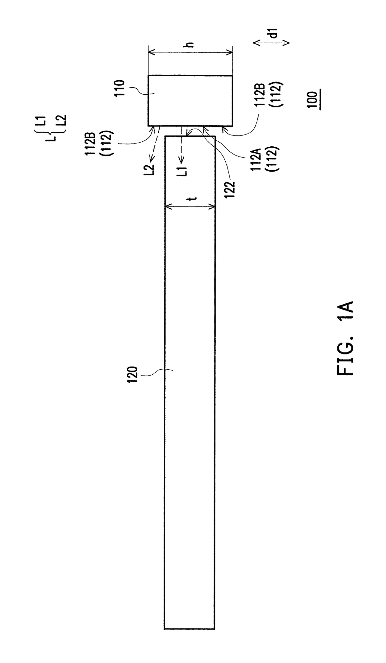
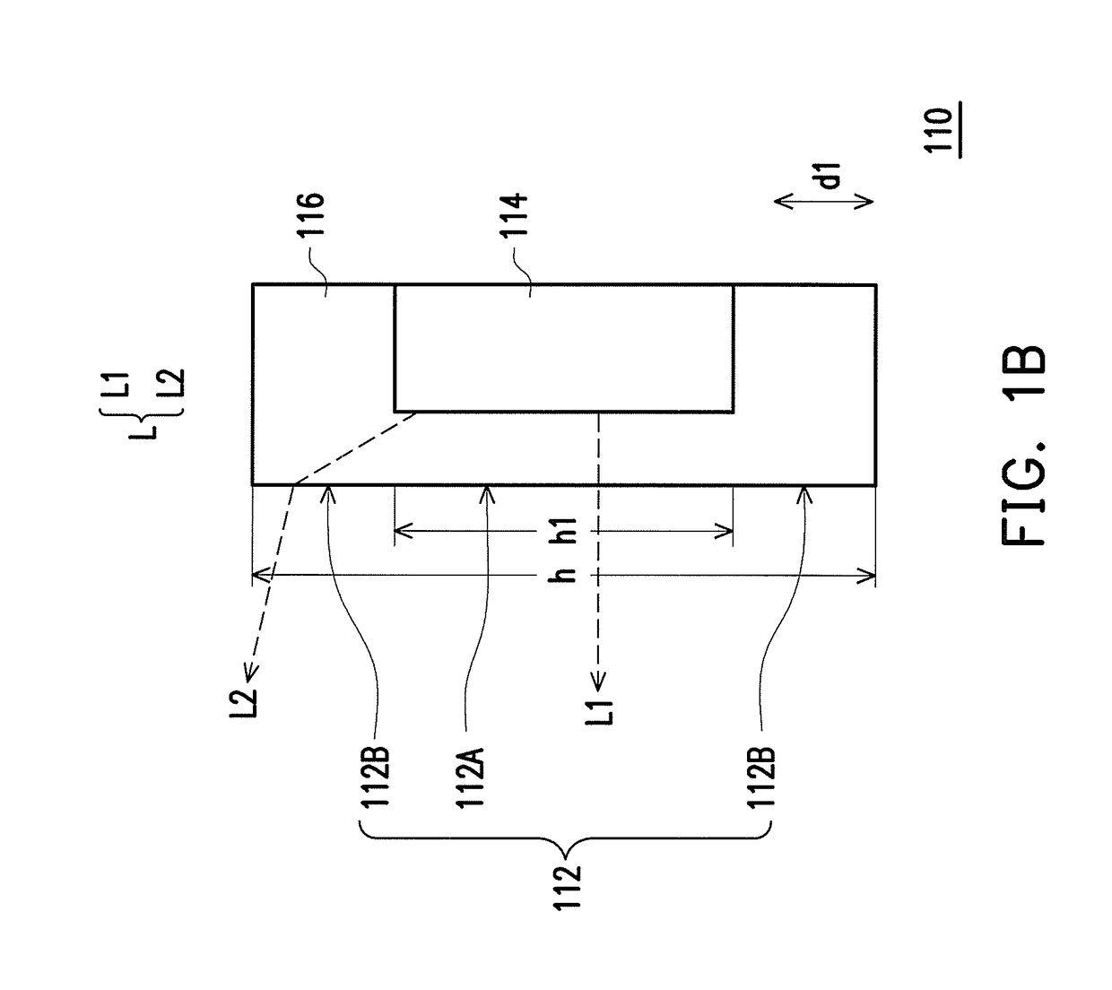
[0025]FIG. 1A is a cross-sectional view illustrating a light emitting module according to a first embodiment of the invention. FIG. 1B is a schematic view illustrating a light emitting unit according to the first embodiment of the invention. Contents of FIGS. 1A and 1B merely serve to illustrate relative relations of respective components. For the clearness of illustration, some components are enlarged. However, FIGS. 1A and 1B do not serve to limit sizes and positions of the components. Referring to FIGS. 1A and 1B, in the first embodiment of the invention, a light emitting module 100 includes at least one light emitting unit 110 and a light guide plate 120. The light emitting unit 110 includes a li...


PUM


Abstract

A light emitting module is provided. A light emitting unit includes a light emitting surface including a middle light emitting area and a peripheral light emitting area. The peripheral light emitting area is disposed on the opposite sides of the middle light emitting area. The light emitting unit emits light from the light emitting surface. A light guide plate includes a light incident surface adjacent to the middle light emitting area. The width of the light incident surface in a direction is smaller than the width of the light emitting surface in the direction, and the light incident surface is configured to receive part of the light that is emitted from the middle light emitting area, and another part of the light that is emitted from the peripheral light emitting area deviates from the light incident surface. A display device is also provided.

Description

CROSS-REFERENCE TO RELATED APPLICATION[0001]This application claims the priority benefits of U.S. provisional application Ser. No. 62 / 078,433, filed on Nov. 12, 2014 and Taiwan application serial no. 104103875, filed on Feb. 5, 2015. The entirety of each of the above-mentioned patent applications is hereby incorporated by reference herein and made a part of this specification.BACKGROUND OF THE INVENTION[0002]1. Field of the Invention[0003]The invention relates to a light source device and an electronic apparatus, and particularly relates to a light emitting module and a display device.[0004]2. Description of Related Art[0005]The main function of a light source module is to provide light for a display device. The basic principle thereof is to use a linear light source or a point light source and convert effective light into a surface light source having a high brightness and a preferable uniformity through a light guide plate. Generally speaking, the light source modules may be categ...

Claims


Application Information

Patent Timeline
Patent Type & Authority Patents(United States)
IPC IPC(8): F21V8/00
CPCG02B6/0073G02B6/0023G02B6/0091G02B6/0013
Inventor TAI, SHENG-CHIEHCHEN, I-JENGHUANG, HSIN-TAO
Owner E INK HLDG INC
Features
  • R&D
  • Intellectual Property
  • Life Sciences
  • Materials
  • Tech Scout
  • Unparalleled Data Quality
  • Higher Quality Content
  • 60% Fewer Hallucinations
Learn More