Connector

a technology of connecting rods and connectors, applied in the direction of coupling bases/cases, coupling device connections, incorrect coupling prevention, etc., can solve the problem of damaging the wall of the female housing, and achieve the effect of accidental movement of the detector

Active Publication Date: 2017-05-30
SUMITOMO WIRING SYST LTD
View PDF13 Cites 12 Cited by
  • Summary
  • Abstract
  • Description
  • Claims
  • Application Information

AI Technical Summary

Benefits of technology

[0008]The invention is directed to a connector with a housing that is connectable to a mating housing. A detector is assembled movably to a standby position and a detection position with respect to the housing and is kept at the standby position until the housings are connected properly, but is movable to the detection position as the housings are connected properly. A biasing member is assembled with the housing and accumulates a biasing force in the process of connecting the two housings to move the detector to the detection position by releasing the biasing force when the housings are connected properly. The detector has a resilient arm that slides on a sliding surface of the housing while being resiliently deformed in the process of reaching the detection position. Thus, a moving speed of the detector is slowed and an impact of the detector reaching the detection position can be alleviated. As a result, the housing will not be damaged.
[0009]The sliding surface of the housing is provided at a position where the resilient arm is slidable thereon before the detector reaches the detection position. Thus, a timing of the detector sliding on the sliding surface of the housing is limited within a short time before reaching the detection position to ensure a smooth movement of the detector.
[0011]The resilient arm has an operating surface that is pressed at the detection position to deform the resilient arm in a direction to be released from locking with the recess. Thus, movement of the detector to the standby position is enabled. According to this, the detector can be brought easily to the standby position by pressing the operating surface.

Problems solved by technology

As described above, the biasing force of the biasing member may detach the detector from the female housing or may damage a wall of the female housing without being stopped at the detection position due to momentum.

Method used


Image

  • Connector
  • Connector
  • Connector

Examples


Embodiment Construction

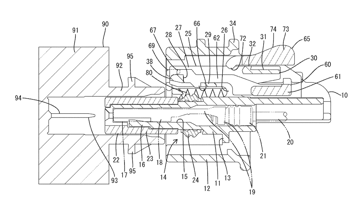
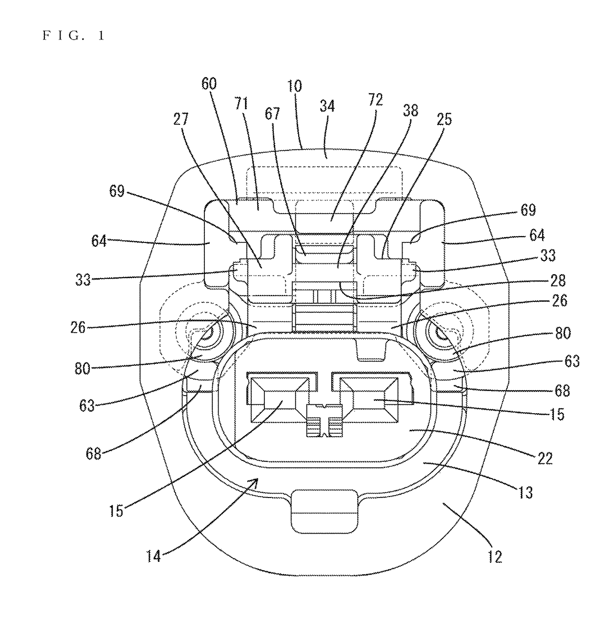
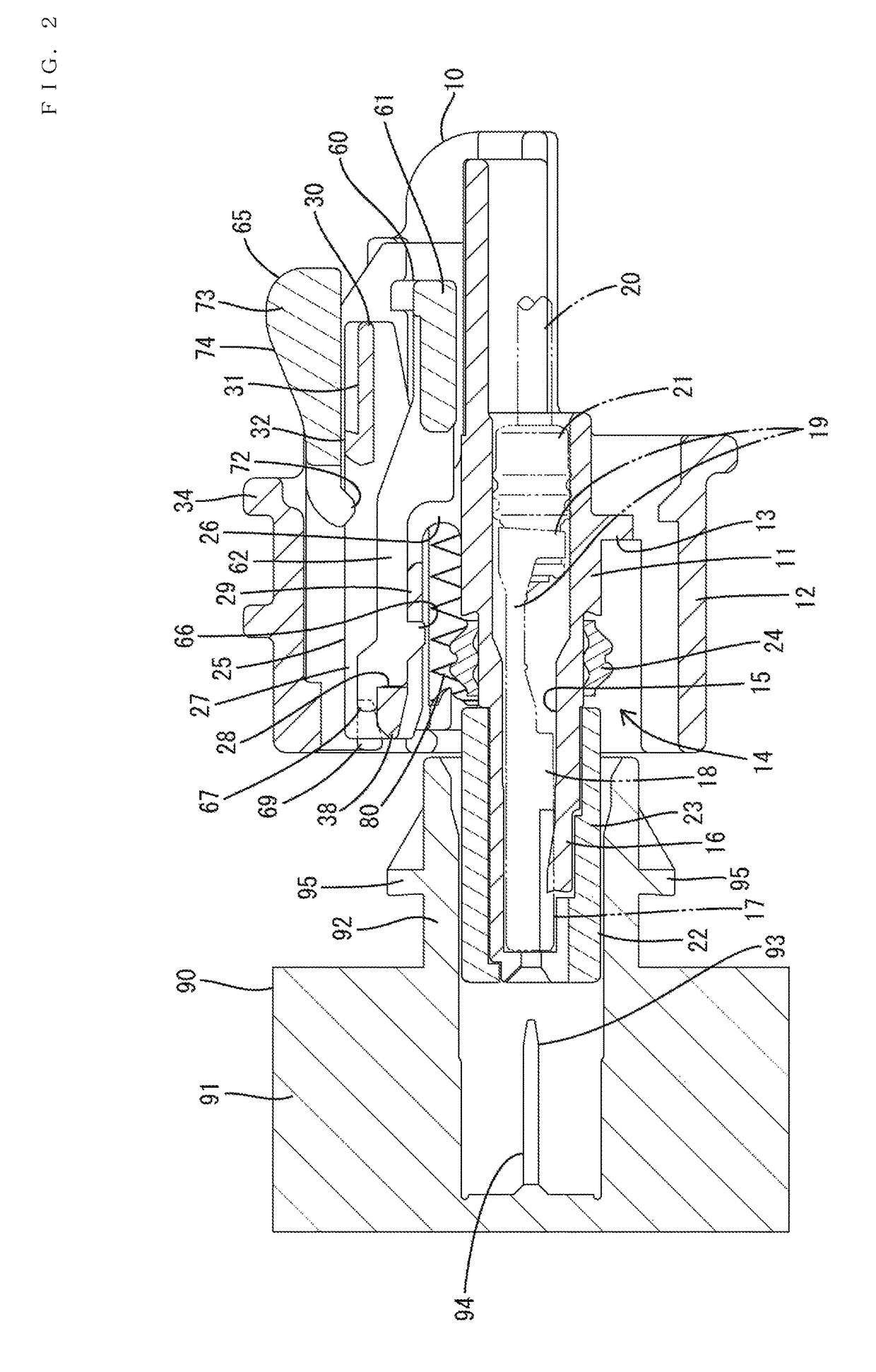
[0027]An embodiment of the invention is described on the basis of FIGS. 1 to 14. A connector of this embodiment includes a housing 10 that is connectable to a mating housing 90. A detector 60 is assembled with the housing 10 and is movable between a standby position and a detection position. Biasing members 80 are mounted in the detector 60 and bias the detector 60 for movement to the detection position. In the following description, surfaces facing each other when the connection of the two housings 10, 90 is started are referred to as the front ends concerning a front-back direction, and a vertical direction is based on figures except FIGS. 8, 9 and 12. A width direction is synonymous with a lateral direction of FIGS. 1, 7, 10 and 11.

[0028]The mating housing 90 is made of synthetic resin and includes a device 91 and a tubular receptacle 92 directly connected to and projecting forward from the device 91, as shown in FIG. 2. Male tabs 94 of mating terminal fittings 93 project into th...


PUM


Abstract

A connector includes a detector (60) movable to a standby position and a detection position with respect to a housing (10). The detector (60) is kept at the standby position in the process of connecting two housings (10, 90) and is biased by biasing members (80) and brought to the detection position when the two housings (10, 90) are properly connected. The detector (60) includes a resilient arm (65) configured to slide on a sliding surface (32) of the housing (10) while being resiliently deformed in the process of reaching the detection position.

Description

BACKGROUND[0001]1. Field of the Invention[0002]The invention relates to a connector.[0003]2. Description of the Related Art[0004]Japanese Patent No. 3225888 discloses a connector with male and female housings that are connectable to each other. A detector is assembled movably to the female housing and a biasing member is interposed between the female housing and the movable member. The male connector housing is provided with a pushing portion.[0005]In the process of connecting the housings, the detector is pushed by the pushing portion and the biasing member is contracted resiliently between the detector and the female housing. Thus, if a connecting operation is stopped halfway, a resilient restoring force of the biasing member accumulated thus far is released to separate the housings and to indicate that the housings are connected incompletely. Thereafter, when the housings are connected properly, the pushing portion is separated from the female housing, the biasing force of the bi...

Claims


Application Information

Patent Timeline
Patent Type & Authority Patents(United States)
IPC IPC(8): H01R13/64H01R13/639
CPCH01R13/64H01R13/639H01R13/6272H01R13/641H01R13/46H01R13/629
Inventor HORIUCHI, HIDEFUMI
Owner SUMITOMO WIRING SYST LTD
Why Eureka
Try Eureka