Viewing system for vehicles, in particular commercial vehicles

a technology for viewing systems and commercial vehicles, applied in closed circuit television systems, television systems, electrical equipment, etc., can solve the problems of difficult or nearly impossible for vehicle drivers to adequately keep accident-critical (accident-prone) areas around commercial vehicles, difficult for drivers to keep all mirrors in view at the same time, obstacles and other vehicles are often difficult to quickly and accurately identify in mirrors, etc., to achieve fewer technical implementation costs

Active Publication Date: 2017-05-30
MEKRA LANG GMBH & CO KG
View PDF121 Cites 5 Cited by
  • Summary
  • Abstract
  • Description
  • Claims
  • Application Information

AI Technical Summary

Benefits of technology

[0016]Starting therefrom, it is an aspect of the present disclosure to provide a simple viewing system for a vehicle, in particular, for a commercial vehicle, that provides an optimal view of areas that are located laterally adjacent to the vehicle and that can depict the fields of view (fields of vision) with a desired reproduction quality in terms of optical distortion.
[0020]The use of a single image capture unit, which is configured for sensing (capturing) both lateral fields of view II and IV (or a first field of view laterally near the vehicle and a second field of view laterally further out from the vehicle), on one vehicle side leads to a simplified viewing system. Thus the computing unit is required to process a smaller amount of (video-) data and can therefore, e.g., improve the real-time display of the captured image. In addition, fewer data connections to the vehicle are needed, since only one image capture unit is provided per vehicle side, which image capture unit is communicatively connected to the computing unit.
[0028]The first legally-prescribed field of view preferably corresponds to a primary (main) mirror field of view, for example, the field of view II (Class II) defined in the UN / ECE Regulation No. 46 for primary (main) mirrors, and the second legally-prescribed field of view preferably corresponds to a wide-angle mirror field of view, for example, the field of view IV for wide-angle exterior mirrors (“Wide-angle” exterior mirror (Class IV)) defined in the UN / ECE Regulation No. 46. Here it is preferred that the main exterior mirror field of view II have only a small amount of distortion, whereas the distortion in the wide-angle external mirror field of view IV is less critical. Since the optical axis extends through the part of the main exterior mirror field of view II that is reproduced on (projected or mapped onto) the digital image sensing unit, the distortion in this part is lowest and can be provided to the driver of the vehicle in the desired degree of quality. The distortion in the wide-angle exterior mirror field of view IV is indeed greater, but due to the above-described fact that this distortion is less critical, the lesser reproduction quality of the wide-angle exterior mirror field of view IV is more acceptable.
[0034]The disclosed viewing system is preferably attached to a vehicle, in particular a commercial vehicle, with the digital image capture unit attached to the vehicle such that it can sense a viewing area on one side of the vehicle with at least one part of a first legally-prescribed field of view and with at least one part of a second legally-prescribed field of view. The image capture unit preferably senses the viewing area with the parts of the first and second legally prescribed field of view from a “bird's-eye” perspective, i.e. an object located in the viewing area is viewed from an eye (ocular) point located obliquely above the object. Using the capture (sensing) of the viewing area from a birds-eye perspective, the driver of the vehicle can view the first and second legally-prescribed field of view in an improved manner and, due to the improved image quality in the reproduced (displayed) part of the first legally-prescribed field of view, recognize traffic obstacles such as pedestrians and other vehicles in a timely manner.
[0037]Furthermore, it can be advantageous that the viewing system includes a further image capture unit that also includes a lens (objective) having an optical axis and a single digital image sensing unit on the opposite side of the vehicle from the first image capture unit. In this case, the further image capture unit is configured to sense a viewing area on the opposite side of the vehicle from the first image capture unit, which area includes at least one part of a first legally-prescribed field of view and at least one part of a second legally-prescribed field of view. In this case, the reproducing (display) unit can be further configured to display the two sensed (captured) viewing areas in a split-screen method so as to be viewable by the driver in the interior of the vehicle. In this case, the sensed viewing area of the driver's side is displayed on the driver's-side on the reproducing unit, and the sensed viewing area of the passenger's side is displayed on the passenger's-side on the reproducing unit. Thus, by looking at the reproducing (display) unit, the driver can view both viewing areas lateral to the vehicle. Alternatively, the viewing areas sensed (captured) on the two sides can be displayed separately from each other on two reproducing (display) units.
[0038]Using the viewing system disclosed herein, it is possible to sense (capture) a first legally-prescribed field of view and a second legally-prescribed field of view, for example the fields of view II and IV (Classes II and IV) defined in the UN / ECE Regulation No. 46, using only one digital image sensing unit, for example a CMOS sensor, while still meeting the requirements of the respective image reproduction qualities. By using only one digital image sensing unit, an economical system is thus disclosed, which further also results in fewer technical implementation costs, since the eccentric arrangement of the above-described elements of the image capture unit can already be incorporated in the development phase. In addition, the adjustment (change-over) for the driver from a wide-angle mirror to the viewing system disclosed herein is non-critical, since using the viewing system disclosed herein, the wide-angle field of view is displayed to the driver with the usual degree of distortion.

Problems solved by technology

Despite the use of prescribed mirrors or devices for indirect viewing (vision), however, it may be very difficult or nearly impossible for a vehicle driver to adequately keep accident-critical (accident-prone) areas around a commercial vehicle in view.
In addition, the presence of multiple mirrors on typical vehicles makes it harder for the driver to keep all mirrors in view at the same time.
Obstacles and other vehicles are often difficult to quickly and accurately identify in a mirror because, despite the specifications of legally-prescribed fields of view, relatively large blind spots still exist.
The orientation of the driver relative to the multiple devices for indirect viewing changes as the driver moves his head and / or shifts his position in his seat, and this increases the likelihood that obstacles will be overlooked, in particular while turning or changing lanes, even though they are reproduced (shown) in the device for indirect viewing (and would be visible to the driver if his head were positioned in an ideal position).
Accidents are thus frequently caused by the fact that drivers of commercial vehicles do not have sufficient viewability into lateral areas of the vehicle, in particular into the one or more blind spots, which are lateral areas adjacent to the vehicle.
However, this can lead to a distortion in each of the respective co-captured fields of view, because these co-captured fields of view do not necessarily lie in the central area.

Method used


Image

  • Viewing system for vehicles, in particular commercial vehicles
  • Viewing system for vehicles, in particular commercial vehicles
  • Viewing system for vehicles, in particular commercial vehicles

Examples


Embodiment Construction

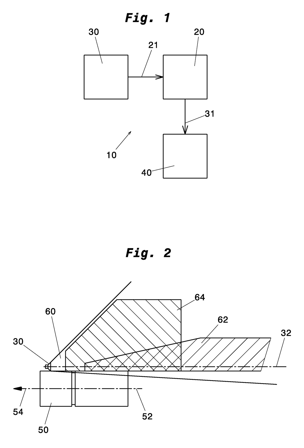
[0044]FIG. 1 schematically shows a viewing system 10. The viewing system 10, which for example can be used in a commercial vehicle such as a truck, comprises at least one image capture unit 30, a computing unit 20, and a reproducing (display) unit 40. The viewing area sensed (captured) by the image capture unit 30 is provided to a computing unit 20 via a first connection 21, for example a data cable suitable for digital transmission of the images captured by the image capture unit 30. The computing unit 20 can be configured to modify the sensed images in a desired manner into a reproduced (displayable) image. For example, the computing unit 20 can process one of the images received from the image capture unit 30 so that certain traffic objects are recognized and identified in the displayed image. The reproduced image modified by the computing unit 20 is then provided to the reproducing unit 40 via a second connection 31, for example a data cable suitable for digital transmission of ...


PUM


Abstract

A viewing system for a vehicle, in particular a commercial vehicle, includes an image capture unit, a computing unit, and a reproducing unit. The image capture unit includes a lens, which has an optical axis, and a digital image sensing unit, and is configured to be attached to the vehicle such that a viewing area on the side of the vehicle is sensed with at least one part of a first legally-prescribed field of view and with at least one part of a second legally-prescribed field of view. The lens is disposed with respect to the digital image sensing unit such that the optical axis extends through the part of the first legally-prescribed field of view that is reproduced on the digital image sensing unit.

Description

CROSS-REFERENCE TO RELATED APPLICATIONS[0001]The present application claims priority from German patent application no. DE 10 2013 002 111.1 filed Feb. 8, 2013, the entire contents of which is incorporated by reference herein.FIELD OF THE INVENTION[0002]The present disclosure is directed to a viewing system for vehicles, in particular commercial vehicles, and, more specifically, to a viewing system including an image capture unit for use in commercial vehicles. Moreover, the present disclosure relates to a vehicle, in particular a commercial vehicle, which is equipped with a viewing system disclosed herein.BACKGROUND[0003]Fields of view (fields of vision) are legally prescribed (defined) for different types of motor vehicles, such as e.g., motorcycles, motor vehicles for transporting passengers, motor vehicles for transporting goods, etc. The fields of view must be provided by a device for indirect viewing, conventionally a mirror, and must be viewable permanently (continuously) and...

Claims


Application Information

Patent Timeline
Patent Type & Authority Patents(United States)
IPC IPC(8): H04N7/18B60R1/00
CPCH04N7/183B60R1/00B60R2300/00B60R1/06H04N7/18B60R1/25
Inventor LANG, WERNERKUNZ, MANUEL
Owner MEKRA LANG GMBH & CO KG
Why Eureka
Try Eureka