Two-shaft gas turbine

a gas turbine and two-shaft technology, applied in the direction of engines, mechanical equipment, machines/engines, etc., can solve the problems of reducing increasing the power of the compressor rotation, and increasing so as to reduce reduce the efficiency of the compressor, and reduce the effect of the nox emission of the combustor

Active Publication Date: 2017-06-06
MITSUBISHI POWER LTD
View PDF7 Cites 0 Cited by
  • Summary
  • Abstract
  • Description
  • Claims
  • Application Information

AI Technical Summary

Benefits of technology

[0007]When the 2-shaft gas turbine has been used for a significant period of time, airborne dust will be attached to compressor blades, leading to decrease in compressor efficiency. This will result in power for the rotation of the compressor to be larger. If the control is exercised to keep the corrected rotating speed or actual rotating speed of the gas generator constant as in JP-A-2011-38531, it is necessary to reduce the angle of the inlet guide vane (IGV) of the compressor to lower the air volume of the compressor. This control cancels out the decrease in compressing power due to the reduced air volume with the increase in the compressing power due to the degradation of the compressor efficiency. The rotating speed can be kept constant accordingly.
[0008]At this time, however, the combustor for the gas generator has its fuel concentration rise because of the lowered air flow rate, making the combustion temperature higher as a consequence. The control above thus has a disadvantage that NOx emission from the combustor increases. In particular, when the output of the power turbine is controlled to be constant as in JP-A-2011-102548, a fuel flow rate increases to compensate for the power decreased according to the reduced air volume. And the NOx emission will further be greater. Additionally, since the performance of the compressor generally tends to be degraded as the angle of the IGV becomes smaller, the control for keeping the rotating speed of the gas generator constant makes the angle of the IGV further smaller, which leads to even larger volume of the NOx emission.
[0009]It is, accordingly, an object of the present invention to provide a 2-shaft gas turbine that can suppress an increase in the NOx emission from a combustor even when compressor efficiency is decreased due to a drop in performance with long-term use.
[0011]The present invention can provide a 2-shaft gas turbine that can suppress an increase in the NOx emission from a combustor even when compressor efficiency is decreased due to a drop in performance with long-term use.

Problems solved by technology

When the 2-shaft gas turbine has been used for a significant period of time, airborne dust will be attached to compressor blades, leading to decrease in compressor efficiency.
This will result in power for the rotation of the compressor to be larger.
This control cancels out the decrease in compressing power due to the reduced air volume with the increase in the compressing power due to the degradation of the compressor efficiency.
The control above thus has a disadvantage that NOx emission from the combustor increases.
Additionally, since the performance of the compressor generally tends to be degraded as the angle of the IGV becomes smaller, the control for keeping the rotating speed of the gas generator constant makes the angle of the IGV further smaller, which leads to even larger volume of the NOx emission.

Method used


Image

  • Two-shaft gas turbine
  • Two-shaft gas turbine
  • Two-shaft gas turbine

Examples


first embodiment

(1) First Embodiment

[0020]Preferred embodiments of the present invention will hereinafter be described with reference to the drawings.

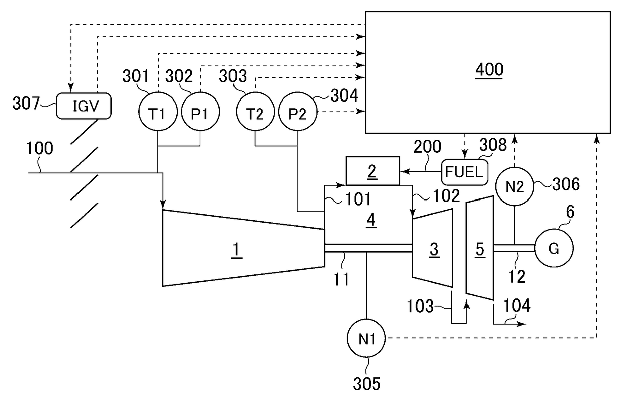
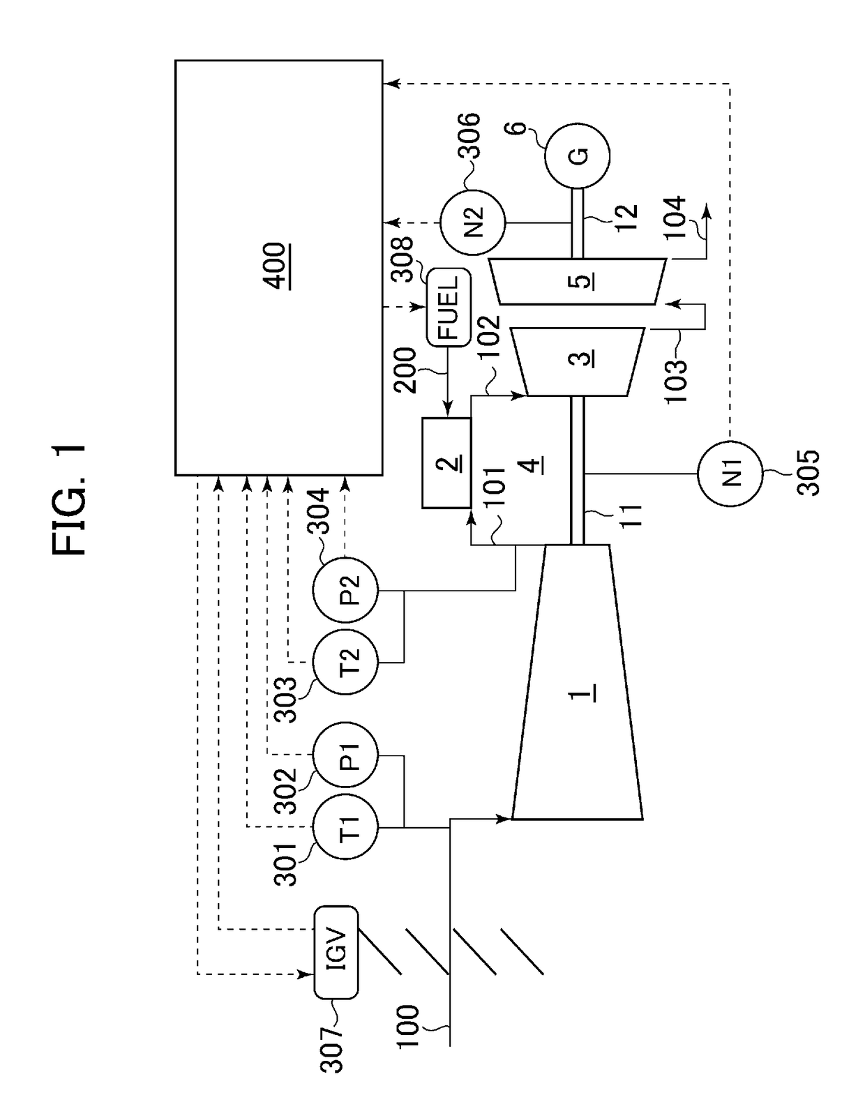
[0021]FIG. 1 is a flow diagram illustrating an overall structure of a 2-shaft gas turbine according to a first embodiment of the present invention. As illustrated in FIG. 1, the 2-shaft gas turbine is mainly constituted of a gas generator 4 and a power turbine 5.

[0022]The gas generator 4 mainly includes a compressor 1, at least one combustor 2 and a high-pressure turbine 3. The compressor 1 compresses air 100 to generate high-pressure air 101 for combustion. The combustor 2 burns the compressed air 101 introduced from the compressor 1 and fuel 200 to generate combustion gas 102. The high-pressure turbine 3 is driven by the combustion gas 102 generated by the combustor 2. The compressor 1 and the high-pressure turbine 3 are connected to each other through a rotating shaft 11 of the gas generator. The compressor 1 is driven by the high-pressure turbine ...

second embodiment

(2) Second Embodiment

[0044]A second embodiment of the present invention will next be described with reference to FIGS. 7 and 8.

[0045]The second embodiment is different from the first one illustrated in FIGS. 6 and 3 corresponding to FIGS. 7 and 8, respectively, in that a first-order lag element 408 is inserted to reduce the temporal variation rate of a target speed through control taking into account the efficiency degradation degree.

[0046]A computing unit 407 in FIG. 7 receives, as an input, an efficiency degradation degree Δη which is the output of the computing unit 404. After computing a deviation of the target speed of the gas generator, the unit outputs the deviation. A specific example is described with reference to FIG. 8.

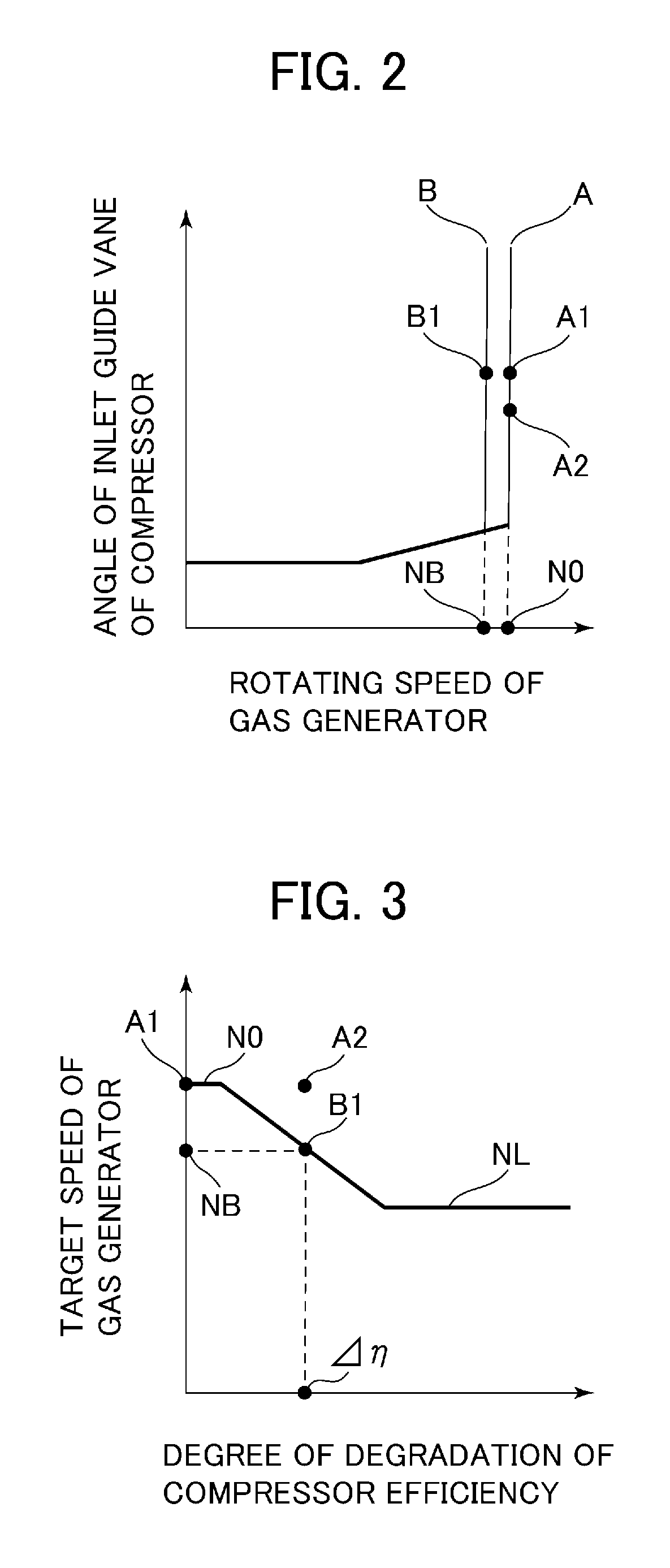
[0047]If compressor efficiency has not decreased (A1), the deviation is computed as 0 as in FIG. 8 so as to make the target speed of the gas generator equal to the target speed “N0” in FIG. 3. The more airborne dust is attached to compressor blades, the lar...


PUM


Abstract

A 2-shaft gas turbine can suppress an increase in NOx emission from a combustor even when degradation of compressor efficiency occurs due to a decrease in performance with long-term use. The 2-shaft gas turbine has a gas generator and a power turbine, and includes a controller configured to set, in accordance with a degree of degradation of compressor efficiency computed from measured control parameters, a target speed of the gas generator at a level lower than a target speed in a state where degradation of the compressor efficiency has not occurred. The controller is configured to control the rotating speed of the gas generator on the basis of a difference between the target speed thus set and an actual rotating speed.

Description

BACKGROUND OF THE INVENTION[0001]1. Field of the Invention[0002]The present invention relates to a 2-shaft gas turbine including a gas generator and a power turbine.[0003]2. Description of the Related Art[0004]A 2-shaft gas turbine mainly includes a gas generator and a power turbine (a low-pressure turbine) connected to a load, the gas generator employing a compressor, at least one combustor, and a high-pressure turbine. The gas generator and the power turbine each have a rotating shaft and both rotating shafts are not connected to each other. In addition, rotating speeds of the gas generator and the power turbine are controlled independently of each other.[0005]JP-2011-38531-A describes a technology relating to a method for controlling the rotating speed of a rotating shaft on the side of a gas generator. Specifically, JP-2011-38531-A discloses the control method having two control modes in order to solve a sympathetic vibration problem caused by an alteration in rotating speed att...

Claims


Application Information

Patent Timeline
Patent Type & Authority Patents(United States)
IPC IPC(8): F02C9/16F02C9/28F02C3/10
CPCF02C9/16F02C3/10F02C9/28F05D2270/20F05D2270/304
Inventor KOGANEZAWA, TOMOMITAKAHASHI, YASUO
Owner MITSUBISHI POWER LTD
Why Eureka
Try Eureka