Methods and systems for detection of blur artifact in digital video due to high quantization

a technology of blur artifacts and quantization, applied in the field of determining blur in a video, can solve the problems of blur artifacts, blurry objects near the edges, pixelation (macroblocking) in the image, etc., and achieve the effect of filtering out noise and high quantization

Active Publication Date: 2017-06-20
INTERRA SYST
View PDF13 Cites 2 Cited by
  • Summary
  • Abstract
  • Description
  • Claims
  • Application Information

AI Technical Summary

Benefits of technology

[0008]In an example embodiment, a method and a system for determining blur in a video comprising at least one image, due to high quantization adopted during encoding of the image, is provided. The method comprises preprocessing of the image to filter out the noise. The method further comprises extraction of an edge image by extraction of gradients of the preprocessed image. An edge direction change image may be determined by utilization of the gradient sign change for each pixel. Further, a maximum absolute gradient magnitude may be determined for each row of the edge image based on the pixel values of each pixel in each row of the edge image. A Principal Edge (PE) image may be determined based on a first set of absolute gradients for each row that are greater than a first predefined percentage of the maximum absolute gradient magnitude for that row. Further, a Highly Significant Edge (HSE) image may be determined based on a second set of absolute gradients for each row that are greater than a threshold. This threshold may be equal to the greater of either a programmable constant or a multiple of the first predefined percentage of the aforementioned maximum absolute gradient magnitude that was computed on a row-by-row basis.
[0009]The method may further comprise detecting ripples around the set of edge pixels of the determined highly significant edge image, for determining a ringing pixel count and a ringing strength aggregate. The detection of the ripples may be based on detection of variations in pixel levels and gradients in the neighbourhood of edges found in the HSE image. Further, a change of gradient direction in a predefined neighbourhood of the highly significant edge pixel may be detected by utilizing the edge direction change image. The change of gradient direction may be directed in a horizontal and a vertical direction. Further, one or more right overshoots that correspond to one or more right troughs and one or more right crests, may be detected. Similarly, one or more left overshoots that correspond to one or more left troughs and one or more left crests, may be detected. The aggregate of ringing pixel count may be determined by incrementing the current value of the ringing pixel count when one of a first set of conditions or a second set of conditions is true. The first set of conditions and a second set of conditions are based on at least a right crest, a right trough, a left crest and a left trough.
[0010]Further, the ringing strength aggregate may be determined by adding the difference between one and a ratio of the difference between corresponding right trough and left trough and the difference between corresponding right crest and left crest. A principal edge thickness aggregate may be determined based on the thickness of each edge present in PE image. Further, a count of principal edge segments is determined by determining total number of edge segments present in the PE image. A ringing metric may be determined based on the ringing pixel count, the ringing strength aggregate, the principal edge thickness aggregate, and the count of the principal edge segments.

Problems solved by technology

The ringing artifacts may result in an appearance of spurious objects near the edges of one or more objects present in the image.
The blockiness artifacts may be caused by use of block-based transforms for compression.
Such block-based transforms may result in pixelation (macroblocking) in the image when the bit rate is low.
Consequently, due to the high QP value, the probability of HF components being quantized to a programmable threshold may increase, thereby leading to introduction of compression artifacts in the image that may be rendered.
The existing methods of compression artifact detection are not robust enough as they do not exhaustively explore the combination of various image parameters in detecting the compression artifacts.

Method used


Image

  • Methods and systems for detection of blur artifact in digital video due to high quantization
  • Methods and systems for detection of blur artifact in digital video due to high quantization
  • Methods and systems for detection of blur artifact in digital video due to high quantization

Examples


Embodiment Construction

[0018]Some embodiments of this disclosure, illustrating all its features, will now be discussed in detail. The words “comprising,”“having,”“containing,” and “including,” and other forms thereof, are intended to be equivalent in meaning and be open ended in that an item or items following any one of these words is not meant to be an exhaustive listing of such item or items, or meant to be limited to only the listed item or items.

[0019]It must also be noted that as used herein and in the appended claims, the singular forms “a,”“an,” and “the” include plural references unless the context clearly dictates otherwise. Although any systems and methods similar or equivalent to those described herein can be used in the practice or testing of embodiments of the present disclosure, the preferred, systems and methods are now described.

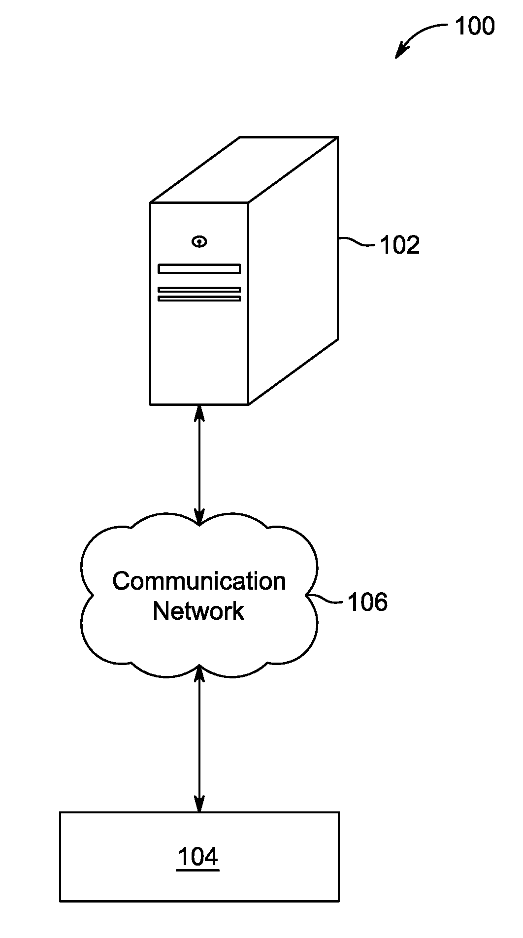
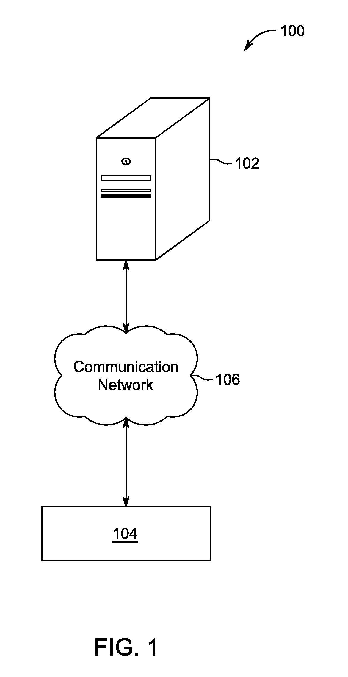
[0020]Embodiments of the present disclosure will be described more fully hereinafter with reference to the accompanying drawings in which like numerals represent ...


PUM


Abstract

A method and system for determining blur in digital video due to high quantization adopted during encoding of an image. The image is preprocessed to filter the noise and an edge image is extracted from the preprocessed image. A gradient sign change is determined for each pixel of the edge image. A ringing metric is determined based on the gradient magnitude and the gradient sign change. Further, a blockiness metric is determined based on a block grid periodicity and offset that is determined based on block grid analysis of the edge image. Further, a perceptual blurriness metric is determined using a mean and kurtosis computed based on a gradient histogram analysis of the block grid analysed edge image. A composite blurring metric is determined based on the blockiness metric, the perceptual blurriness metric, and ringing metric.

Description

FIELD OF THE DISCLOSURE[0001]The present disclosure is generally related to determining blur in a video and more particularly to determining blur in digital video due to high quantization adopted during encoding of the image.BACKGROUND[0002]The subject matter discussed in the background section should not be assumed to be prior art merely as a result of its mention in the background section. Similarly, a problem mentioned in the background section or associated with the subject matter of the background section should not be assumed to have been previously recognized in the prior art. The subject matter in the background section merely represents different approaches, which in and of themselves may also correspond to implementations of the claimed technology.[0003]Recent advancements in the field of media processing have led to development of various algorithms for detection of compression artifacts in an image. Such techniques for detection of compression artifacts may be spatial do...

Claims


Application Information

Patent Timeline
Patent Type & Authority Patents(United States)
IPC IPC(8): G06K9/40H04N5/208G06T5/00H04N5/21
CPCH04N5/21H04N5/208G06T5/003G06T2207/20201G06T2207/10016H04N19/80H04N19/865
Inventor MOGRE, ADVAIT MADHAVKUMAR, BHUPENDERALAM, PERVEZGUPTA, RISHIMADNANI, SHEKHAR
Owner INTERRA SYST
Why Eureka
Try Eureka