Biological-specimen observation apparatus

a technology of biological specimens and observation apparatuses, applied in the field of biological specimen observation apparatuses, can solve the problems of inability to associate images, fluorescent materials and clear, highly quantitative images of fluorescent materials with each other, and achieve the effect of high quantitativ

Inactive Publication Date: 2014-07-29
OLYMPUS CORP
View PDF25 Cites 4 Cited by
  • Summary
  • Abstract
  • Description
  • Claims
  • Application Information

AI Technical Summary

Benefits of technology

[0010]The present invention is made in consideration of the above-described circumstances. Accordingly, it is an object of the present invention to provide a biological-specimen observation apparatus that allows observation of the distribution of a fluorescent material in a specimen and acquisition of the fluorescent material as clear, highly quantitative image data.
[0021]The present invention offers the advantages in that the distribution of a fluorescent material in a specimen can be observed and the fluorescent material can be obtained as clear, highly quantitative image data.

Problems solved by technology

However, the observation apparatus disclosed in Japanese Unexamined Patent Application, Publication No. 2005-316362 has a disadvantage of being unable to associate an image showing the distribution of a fluorescent material and a clear, highly quantitative image of the fluorescent material with each other.
The image acquisition apparatuses disclosed in Japanese Translation of PCT International Application, Publication No. 2003-536052 and the observation apparatuses disclosed in U.S. Pat. No. 5,650,135 have a disadvantage of being unable to perform clear, highly quantitative fluorescence observation because they observe a specimen using a macroimage in which an entire specimen is acquired.

Method used


Image

  • Biological-specimen observation apparatus
  • Biological-specimen observation apparatus
  • Biological-specimen observation apparatus

Examples


first embodiment

[0048]Referring to FIGS. 1 to 4C, a biological-specimen observation apparatus 1 according to the present invention will be described hereinbelow.

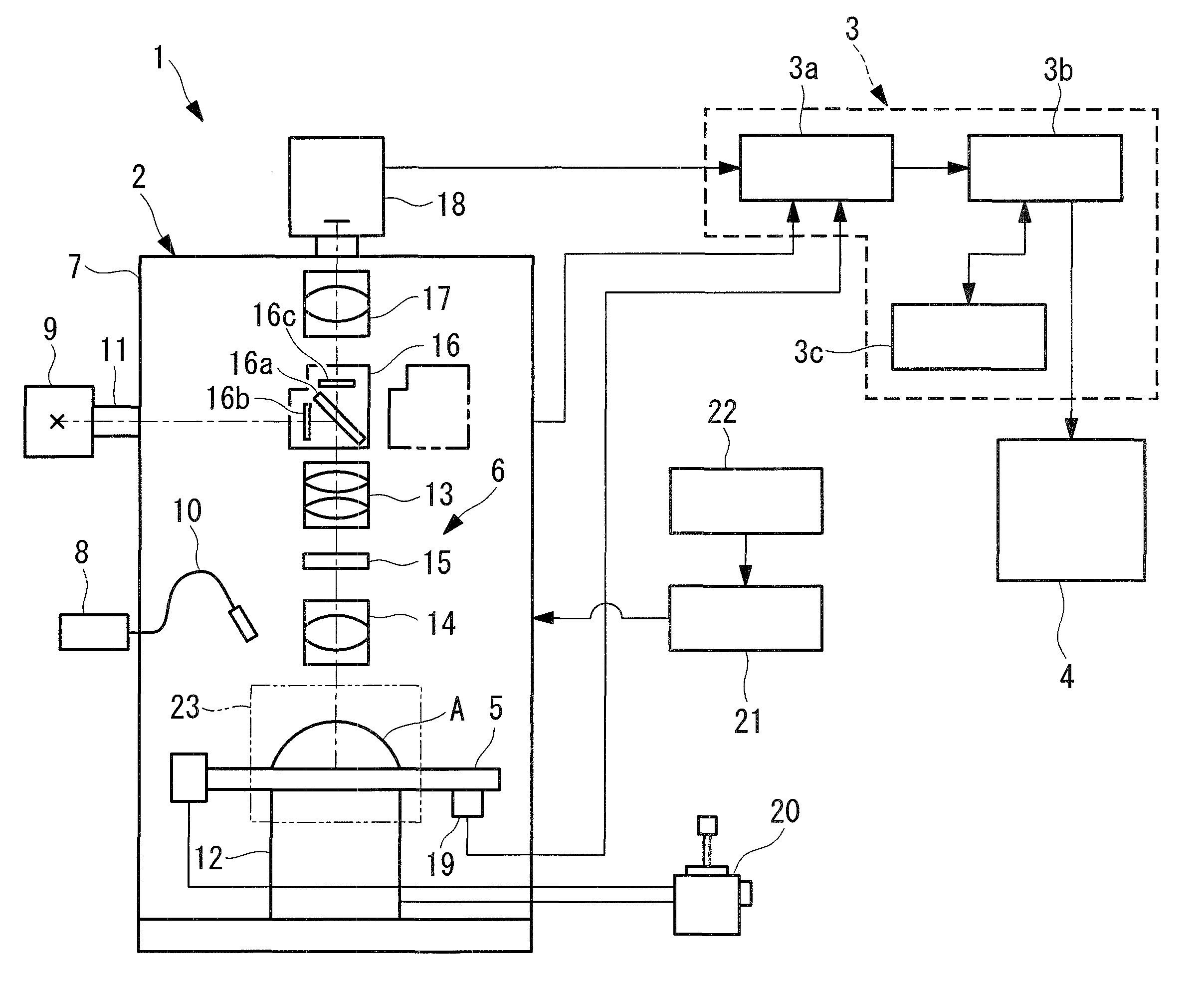
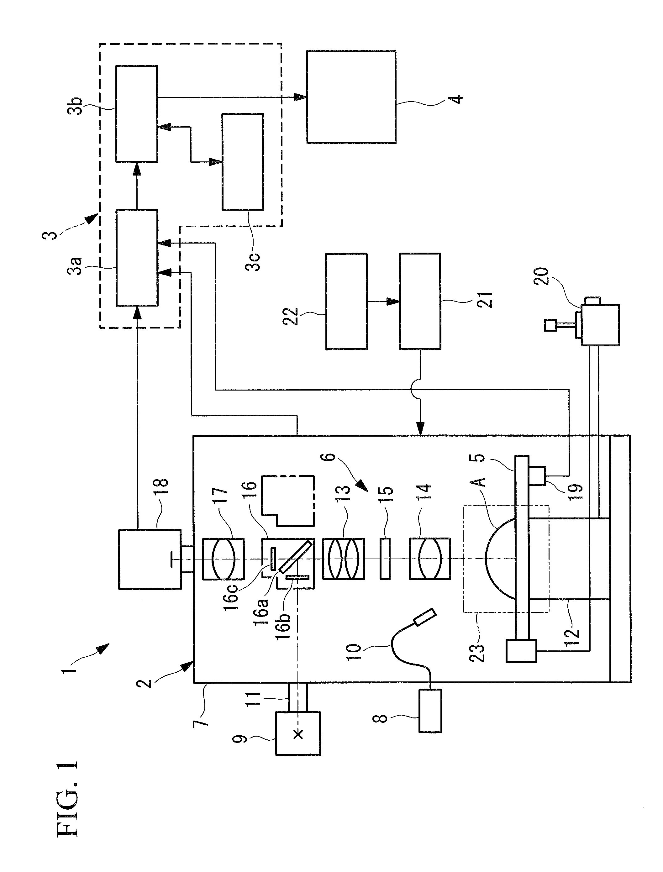
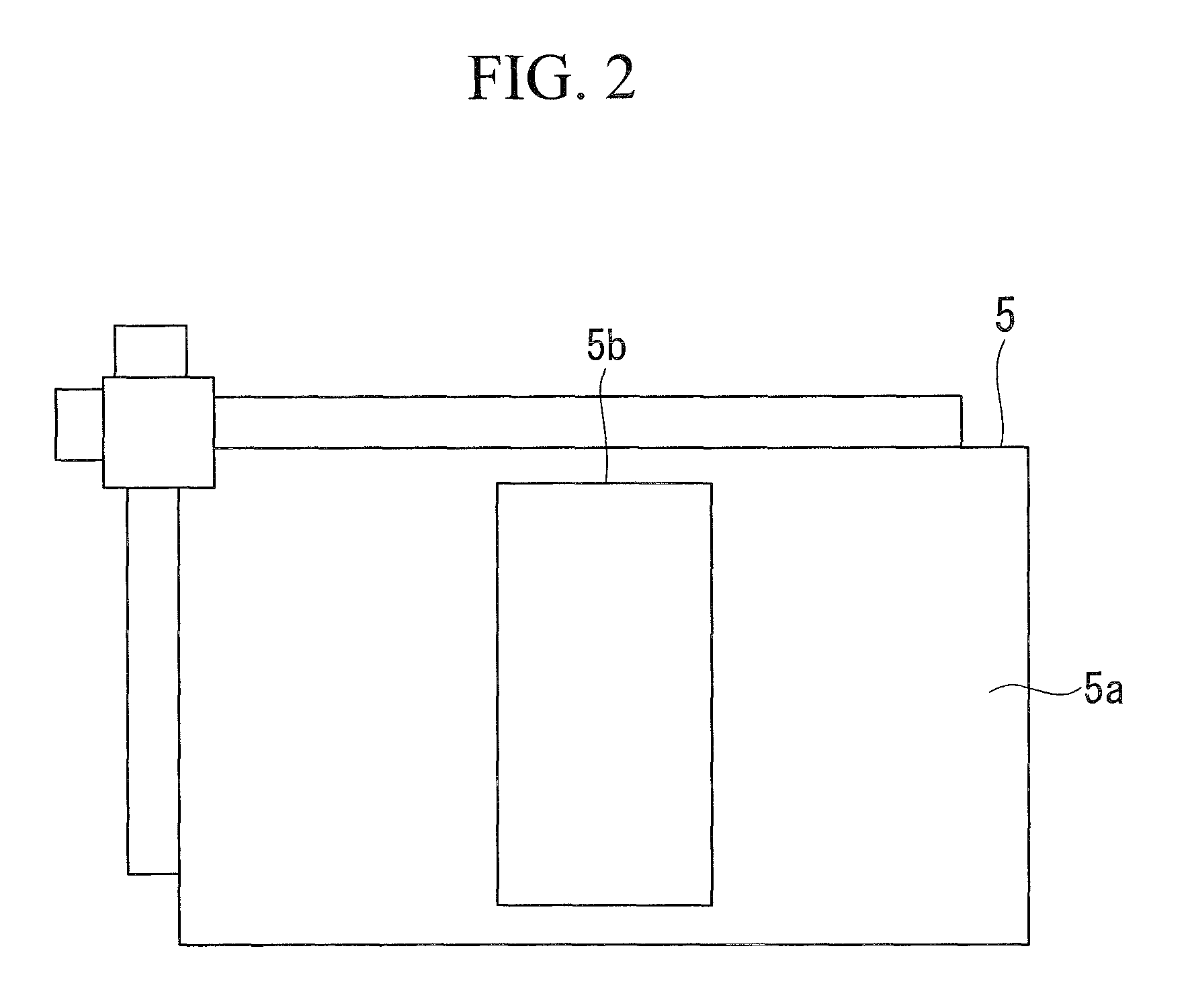
[0049]As shown in FIG. 1, the biological-specimen observation apparatus 1 according to this embodiment is provided with an observation-apparatus main body 2, a control unit 21 that controls the observation apparatus, an operation storage unit 22 that provides a predetermined operation program to the control unit 21, an image control unit 3, and a display 4. The observation-apparatus main body 2 is provided with a stage 5 on which a specimen A, such as a small laboratory animal, for example, a mouse, is mounted, an observation optical system 6, and a case 7 that accommodates the observation optical system 6 to shield it from light.

[0050]The observation optical system 6 is provided with a visible-light source 8 that emits visible light for bright-field observation, an excitation-light source 9 that emits excitation light for fluorescence obse...

second embodiment

[0095]Referring to FIGS. 8, 9A, 9B and 9C, a biological-specimen observation apparatus 201 according to the present invention will be described hereinbelow.

[0096]In the description of this embodiment, components having a configuration common to the above-described biological-specimen observation apparatus 1 according to the first embodiment are given the same reference numerals, and descriptions thereof will be omitted.

[0097]As shown in FIG. 8, the biological-specimen observation apparatus 201 according to this embodiment is not provided with the zooming optical system 13 but is provided with a plurality of switchable objective lenses 14 and 203 having different focal distances. These objective lenses 14 and 203 are held by a revolver 204 so as to be selectively inserted in and removed from the observation optical system 6.

[0098]The objective lenses 14 and 203 have a viewing region as shown in FIGS. 9A, 9B and 9C. As shown in FIG. 9B, the objective lens 14 for observing the fluoresc...

third embodiment

[0105]Next, referring to FIG. 11, a biological-specimen observation apparatus 301 according to the present invention will be described hereinbelow.

[0106]Also in the description of this embodiment, components having a configuration common to the above-described biological-specimen observation apparatus 1 according to the first embodiment are given the same reference numerals, and descriptions thereof will be omitted.

[0107]The biological-specimen observation apparatus 301 according to this embodiment is not provided with the focusing mechanism 12 for moving the stage 5 in the direction along the optical axis of the objective lens 14 but is provided with a linear motion mechanism 303 for moving the image-forming lens 17 in the direction along the optical axis. The linear motion mechanism 303 includes, for example, a linear motion guide having a motor serving as a driving source, a rail, and a slider, and a rack-and-pinion mechanism for transferring a driving force from the motor to the...


PUM


Abstract

The distribution of a fluorescent material in a specimen can be observed and the fluorescent material can be obtained as clear, highly quantitative image data. A biological-specimen observation apparatus is provided which comprises a stage on which a specimen is mounted; a position detector, provided on the stage, that detects the position of the specimen; a light source that emits excitation light or illumination light onto the specimen mounted on the stage; an objective lens, disposed opposing the stage, that collects fluorescence or reflected light from the specimen; an image-forming lens that forms an image on the specimen, collected by the objective lens; an image acquisition unit that acquires the image on the specimen, formed by the image-forming lens; an image storage unit that stores the image obtained by the image acquisition unit and positional information of the specimen detected by the position detector in association with each other; and an image processing unit that performs combining processing of a plurality of the images stored by the image storage unit on the basis of the positional information stored in association with the images.

Description

BACKGROUND OF THE INVENTION[0001]1. Field of the Invention[0002]The present invention relates to a biological-specimen observation apparatus.[0003]This application is based on Japanese Patent Application Nos. 2007-333870 and 2008-162127, the content of which is incorporated herein by reference.[0004]2. Description of Related Art[0005]A known observation apparatus in the related art is capable of both observation of the distribution of a fluorescent material in a specimen and acquisition of clear, highly quantitative images of the fluorescent material by switching between an objective lens and an image-forming lens to achieve a broad range of magnification (for example, refer to Japanese Unexamined Patent Application, Publication No. 2005-316362).[0006]Furthermore, a known image acquisition apparatus in the related art displays the distribution of a fluorescent material in a specimen by obtaining and storing a bright field image and a luminous image and automatically generating an im...

Claims


Application Information

Patent Timeline
Patent Type & Authority Patents(United States)
IPC IPC(8): G21K5/10
CPCG01N21/645G01N2021/6421G01N2021/6493
Inventor HONDA, SUSUMUNAKAJIMA, CHIKA
Owner OLYMPUS CORP
Why Eureka
Try Eureka