Crowbar current elimination

a current elimination and crowbar technology, applied in the field of electronic devices, can solve the problems of low-power oscillators required to operate at sub-a currents, extremely slow rise/fall times at internal nodes, and difficult to achieve the effect of reducing the number of crowbar currents

Active Publication Date: 2017-06-27
LATTICE SEMICON CORP
View PDF4 Cites 2 Cited by
  • Summary
  • Abstract
  • Description
  • Claims
  • Application Information

AI Technical Summary

Problems solved by technology

Micropower circuits such as bandgaps, low-power oscillators, and other analog circuits operate at bias currents of a few nanoamps or less, which results in slow rise / fall times at internal nodes due to unavoidable parasitic capacitances.
This is extremely slow compared to sub-100 ps gate delays in modern technologies.
A low-power oscillator required to operate at sub-μA currents presents a challenge due to its output switching behavior required to drive some clocked, digital circuits.
The transition from slow rise / fall times within micropower analog circuitry to fast rise / fall times required to clock digital circuits is the challenge for maintaining very low-power operation.
Slow rise / fall times at the gates of digital cells such as inverters can result in very significant time per clock cycle during which both PMOS and NMOS transistors are conducting.
The PMOS is sourcing current from the positive supply while the NMOS is sinking current to the negative supply, resulting in significant loss of current needed to drive the load at the gate output.
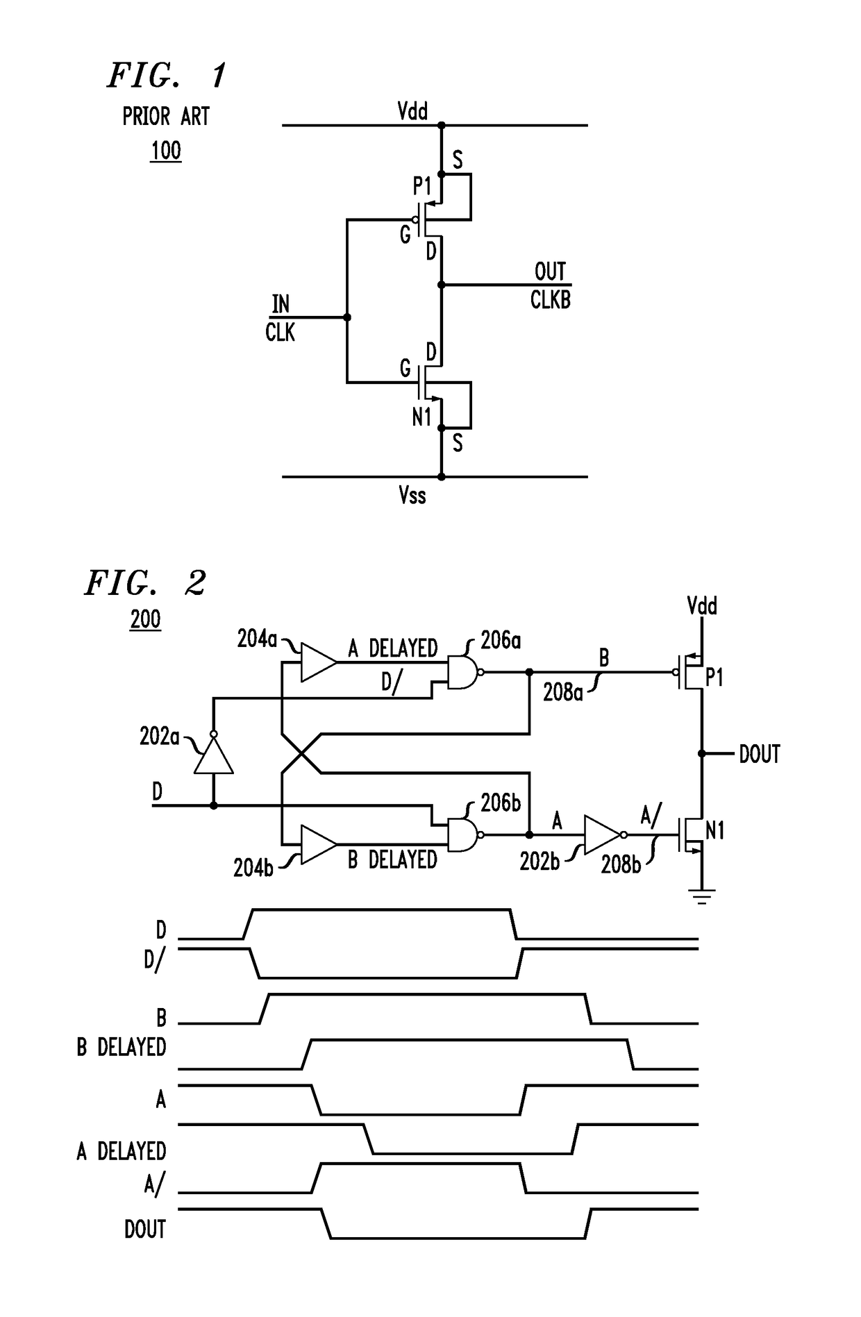
This technique has two limitations where a wide frequency range is required.
The fixed delays severely limit the upper range of operation.

Method used


Image

  • Crowbar current elimination
  • Crowbar current elimination
  • Crowbar current elimination

Examples


Embodiment Construction

[0025]Detailed illustrative embodiments of the present invention are disclosed herein. However, specific structural and functional details disclosed herein are merely representative for purposes of describing example embodiments of the present invention. The present invention may be embodied in many alternate forms and should not be construed as limited to only the embodiments set forth herein. Further, the terminology used herein is for the purpose of describing particular embodiments only and is not intended to be limiting of example embodiments of the invention.

[0026]As used herein, the singular forms “a,”“an,” and “the,” are intended to include the plural forms as well, unless the context clearly indicates otherwise. It further will be understood that the terms “comprises,”“comprising,”“includes,” and / or “including,” specify the presence of stated features, steps, or components, but do not preclude the presence or addition of one or more other features, steps, or components. It ...


PUM


Abstract

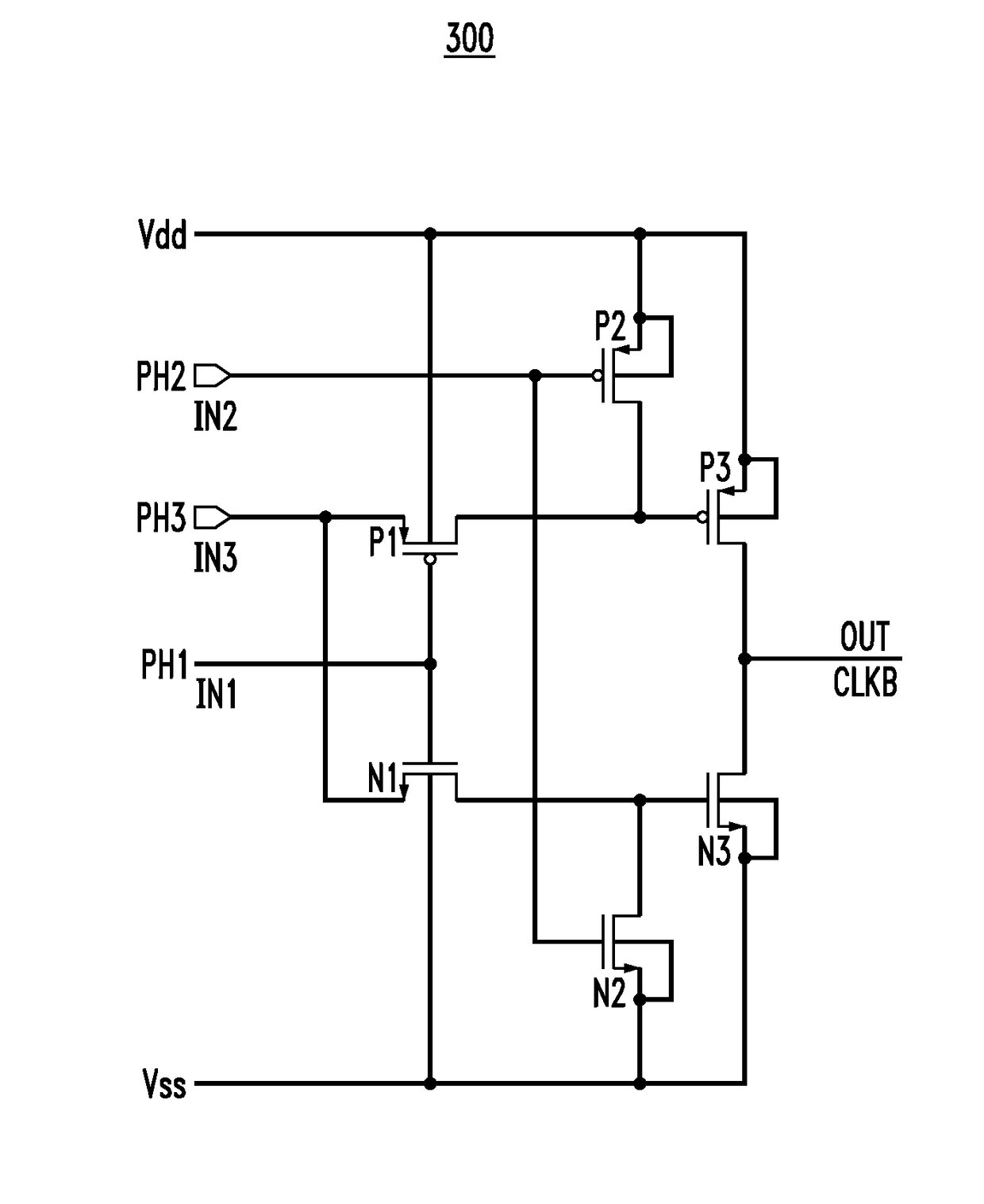
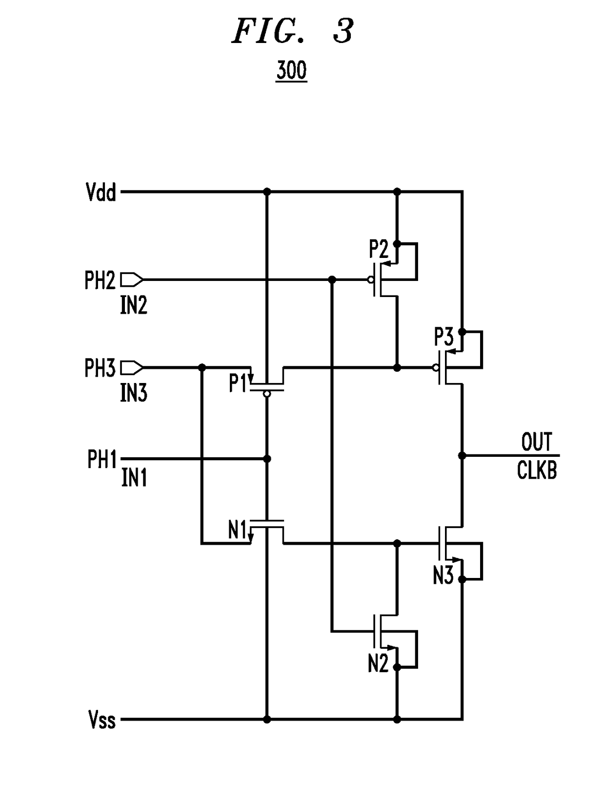
In one embodiment, an inverter generates an inverted clock signal using (i) first P-type and N-type transistors connected in cascode between supply and ground nodes and (ii) control circuitry receiving different phase-offset input clock signals that ensure that the cascode-connected transistors are never even partially on at the same time, thereby preventing crowbar current from occurring through the cascode-connected devices. In one implementation, the control circuitry has two P-type transistors and two N-type transistors configured to receive three phase-offset input clock signals to prevent crowbar current in the inverter. The control circuitry has pass transistors that selectively allow one of the phase-offset input signals to be applied to the gate of one of the cascode-connected transistors with minimal delay, thereby enabling the inverter to operate properly over a relatively wide range of input clock frequencies.

Description

BACKGROUND[0001]Field of the Invention[0002]The present invention relates to electronics and, more specifically but not exclusively, to schemes for avoiding crowbar current in CMOS micropower circuits.[0003]Description of the Related Art[0004]This section introduces aspects that may help facilitate a better understanding of the invention. Accordingly, the statements of this section are to be read in this light and are not to be understood as admissions about what is prior art or what is not prior art.[0005]Modern integrated circuit design is dominated by complementary metal oxide semiconductor (CMOS) technology, which combines N-type MOS (NMOS) and P-type MOS (PMOS) transistors in addition to a smaller number of other structures which add design flexibility. Micropower circuits such as bandgaps, low-power oscillators, and other analog circuits operate at bias currents of a few nanoamps or less, which results in slow rise / fall times at internal nodes due to unavoidable parasitic capa...

Claims


Application Information

Patent Timeline
Patent Type & Authority Patents(United States)
IPC IPC(8): H03K17/00H03K19/00
CPCH03K19/0013
Inventor MILLER, EDWARD
Owner LATTICE SEMICON CORP
Why Eureka
Try Eureka