
Glass run

a glass run and run technology, applied in the field of glass runs, can solve the problems of reducing the concave space, affecting the sound quality of the engine, so as to reduce the sound pressure level of the sound

Active Publication Date: 2017-07-04
NISHIKAWA RUBBER
View PDF30 Cites 8 Cited by
  • Summary
  • Abstract
  • Description
  • Claims
  • Application Information

AI Technical Summary

Benefits of technology

[0025]Partially providing the noise insulation wall, only on the end part of the inner-cabin side wall or only around the end part for example, accomplishes a sufficient noise insulation effect.
[0026]Alternatively, costly though it is, the noise insulation wall may be continuously provided from the end part of the inner-cabin side wall or around the end part over the base root of the inner lip for covering up the concave space, thereby reducing the concave space. In this case, the noise insulation wall reduces the space for the sound, which penetrates the door glass, to enter as well as shades the sound, which echoes in the concave space and is amplified, to be emitted inside the automobile.
[0031]When arranging the inner lip to connect with the end part on the side of the connecting wall of the noise insulation wall, the distance between the door glass and the noise insulation wall is preferably within the above-mentioned range for reducing the sound pressure level of the sound which penetrates the door glass. But when a distance is zero touch between the door glass and the base root of the inner lip which extends toward the outer-cabin side from the end part on the side of the connecting wall of the noise insulation wall, the inner lip is subjected to over compression with respect to the door glass. Accordingly, for preventing the over compression, the distance is preferably not less than 1 mm between the door glass and at least a part of the noise insulation wall, which connects with the base root of the inner lip.

Problems solved by technology

The structure hampers quietness.
The structure also hampers quietness.
Alternatively, costly though it is, the noise insulation wall may be continuously provided from the end part of the inner-cabin side wall or around the end part over the base root of the inner lip for covering up the concave space, thereby reducing the concave space.
Accordingly, the structure is not favorable.
But the lip makes elastic contact with the door glass, which is not a favorable structure.

Method used


Image

  • Glass run
  • Glass run
  • Glass run

Examples


Embodiment Construction

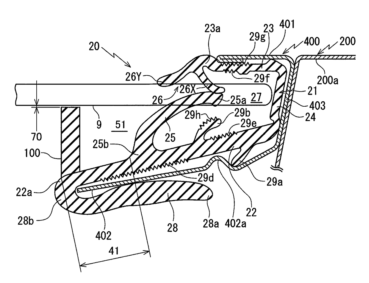
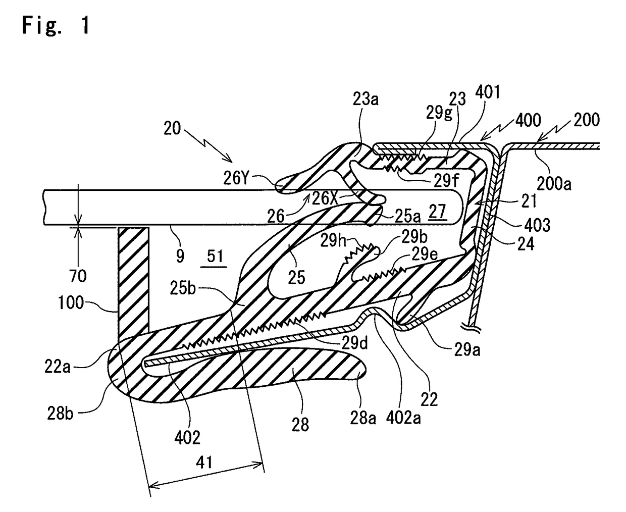
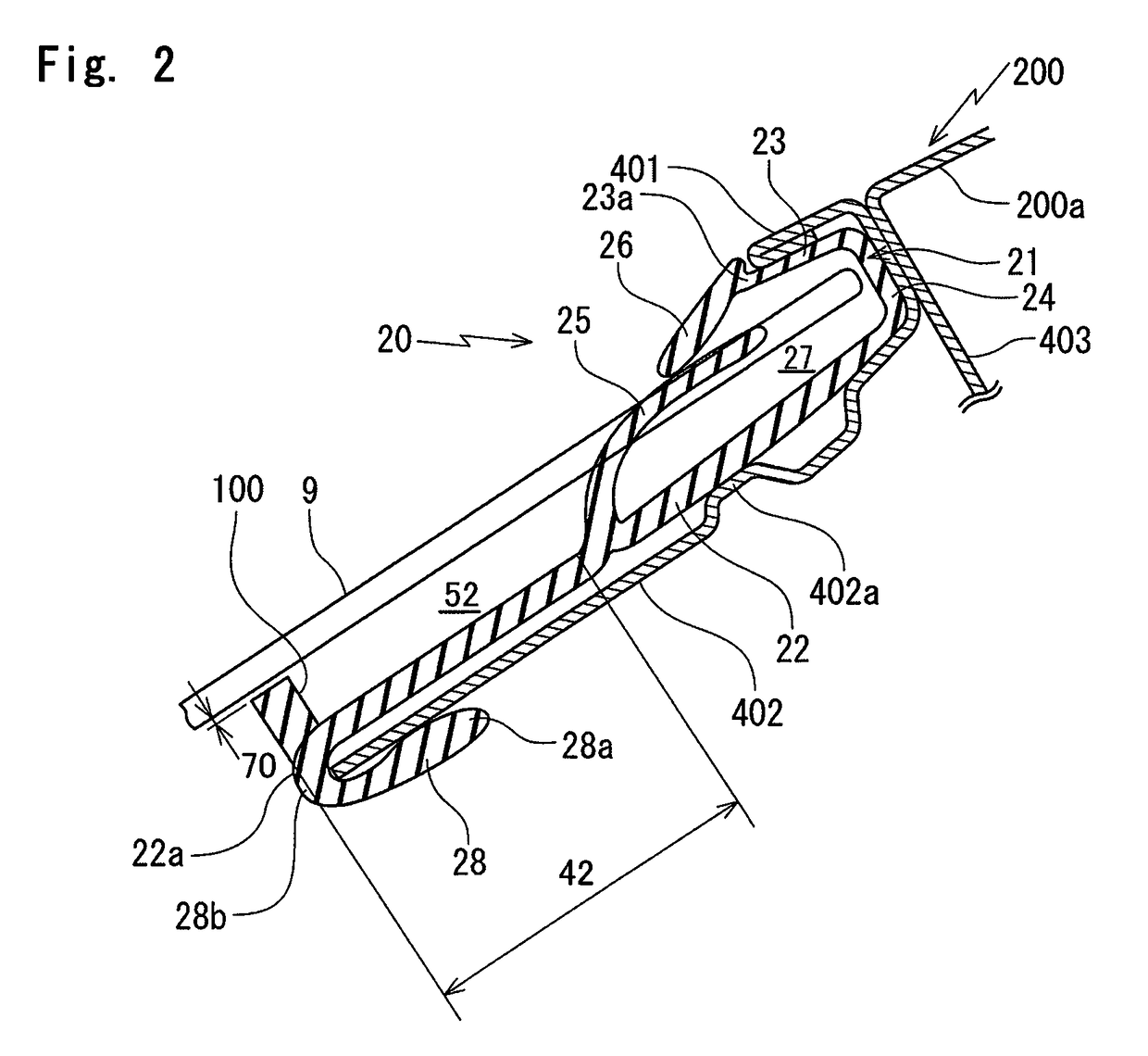
[0048]Referring to FIG. 1 to FIG. 3, a glass run according to an embodiment of the present invention will be described.

[0049]FIG. 1 shows a state that a glass run 20 according to the embodiment of the present invention is assembled on a door sash (frame) 400. FIG. 1 corresponds to an I-I line enlarged cross section of FIG. 12 and FIG. 2 corresponds to a II-II line enlarged cross section of FIG. 12. When constituents or items correspond to those in prior arts, the same symbols are used.

[0050]The glass run 20 of the present invention is fittable along the door sash (frame) 400 mounted on a door panel 200a of a press door type front door 200 (or a rear door 300 in the same manner) by spot welding. The glass run 20 guides a door glass 9 lifting or lowering into a channel 27.

[0051]The glass run 20 of FIG. 1, as employed in FIG. 12 is applied on a rear side vertical edge part 12 which extends upward from an inner part of the door panel 200a of the front door 200 and is positioned vertical...


PUM


Abstract

A glass run for guiding a door glass in a frame includes: a body having a substantially U-shaped cross-section including an outer-cabin side wall, an inner-cabin side wall longer than the outer-cabin side wall in cross section and a connecting wall which connects the side walls; an outer lip and an inner lip which are slidably brought into contact with the door glass; and a holding lip which extends from an end part of the inner-cabin side wall for fastening an inner-cabin side part of the frame together with the inner-cabin side wall. A noise insulation wall protrudes at least on the end part of the inner-cabin side wall for closing a concave space between an inner-cabin side surface of the door glass and the inner-cabin side wall.

Description

CROSS REFERENCE TO RELATED APPLICATION[0001]This application claims the benefit under 35 USC §119 of JP Patent Applications JP 2015-113540 filed Jun. 3, 2015 and JP2016-032971 filed Feb. 24, 2016, the entire disclosure of which is incorporated herein by reference.BACKGROUND INFORMATION[0002]The present invention relates to a glass run which is fittable along a door sash (frame) of an automobile door for guiding the door glass lifting or lowering.[0003]As shown in FIG. 11, an ordinary glass run 20 has been fit on a door sash (frame) 400 of a front door 200 and a rear door 300 of an automobile for guiding a door glass 9 lifting or lowering.[0004]FIG. 12 shows the glass run 20 operatively coupled on a side of the front door 200. The glass run 20 includes: a front side vertical edge part 11 and a rear side vertical edge part 12, which extend upward from an inner part of a door panel 200a of the front door 200; and a cross edge part 13 which connects upper ends of the two vertical edge p...

Claims


Application Information

Patent Timeline
Patent Type & Authority Patents(United States)
IPC IPC(8): B60J5/04B60J10/74B60J10/32B60J10/50
CPCB60J10/74B60J10/32B60J10/50
Inventor KAMEOKA, TAISUKEEMORI, SHINICHIRO
Owner NISHIKAWA RUBBER
Learn More