Support for use in mine

a technology for supporting and mines, applied in earth-moving drilling, props/chocks, mining structures, etc., can solve the problems of only functioning installations, constant danger in underground mining, time-consuming installation, etc., and achieve the effect of maximising the for

Active Publication Date: 2017-07-04
BURRELL MINING PRODS
View PDF19 Cites 0 Cited by
  • Summary
  • Abstract
  • Description
  • Claims
  • Application Information

AI Technical Summary

Benefits of technology

[0015]As is apparent from the foregoing, in certain embodiments of the support, when in use, the arrangement can provide for a preloading of the structure to be supported. In the particular application of providing support for a mine roof this can be particularly advantageous. The roof strata in most underground mines is made up of laminations of compressed stone, rock, clay, mud and, in some cases, coal material. Materials that are laminated together provide a very strong support structure. A first principle in underground mining is to ensure that those laminates remain strongly bonded together and do not separate under load. The support provides a high degree of clamping pressure to maintain strata laminations and strengthen the roof.
[0017]Furthermore, as described in certain embodiments, the pressure responsive system is disposed within the cavities and comprises two barrier walls, which are axially displaceable relative to one another with a pressure chamber therebetween which can convert a small force into a much larger force, capable of doing work. By arranging the system within the support, the work done is, extends the length of the support and applying a clamping force to the roof strata. The configuration ensures that all available area within the support is utilized to maximise the force that can be generated.

Problems solved by technology

There is a constant danger in underground mining of the collapse of the mine tunnel.
Furthermore, such installations can only function following the separation of strata and the convergence of the roof or when the heave of floor has begun before they begin to function in the designed manner.
The problems associated with supports of this type are that they are time consuming to install.
Furthermore, it only provides a passive support arrangement in that it needs a subsidence to occur before it will commence to load the mine roof.

Method used


Image

  • Support for use in mine
  • Support for use in mine
  • Support for use in mine

Examples


Embodiment Construction

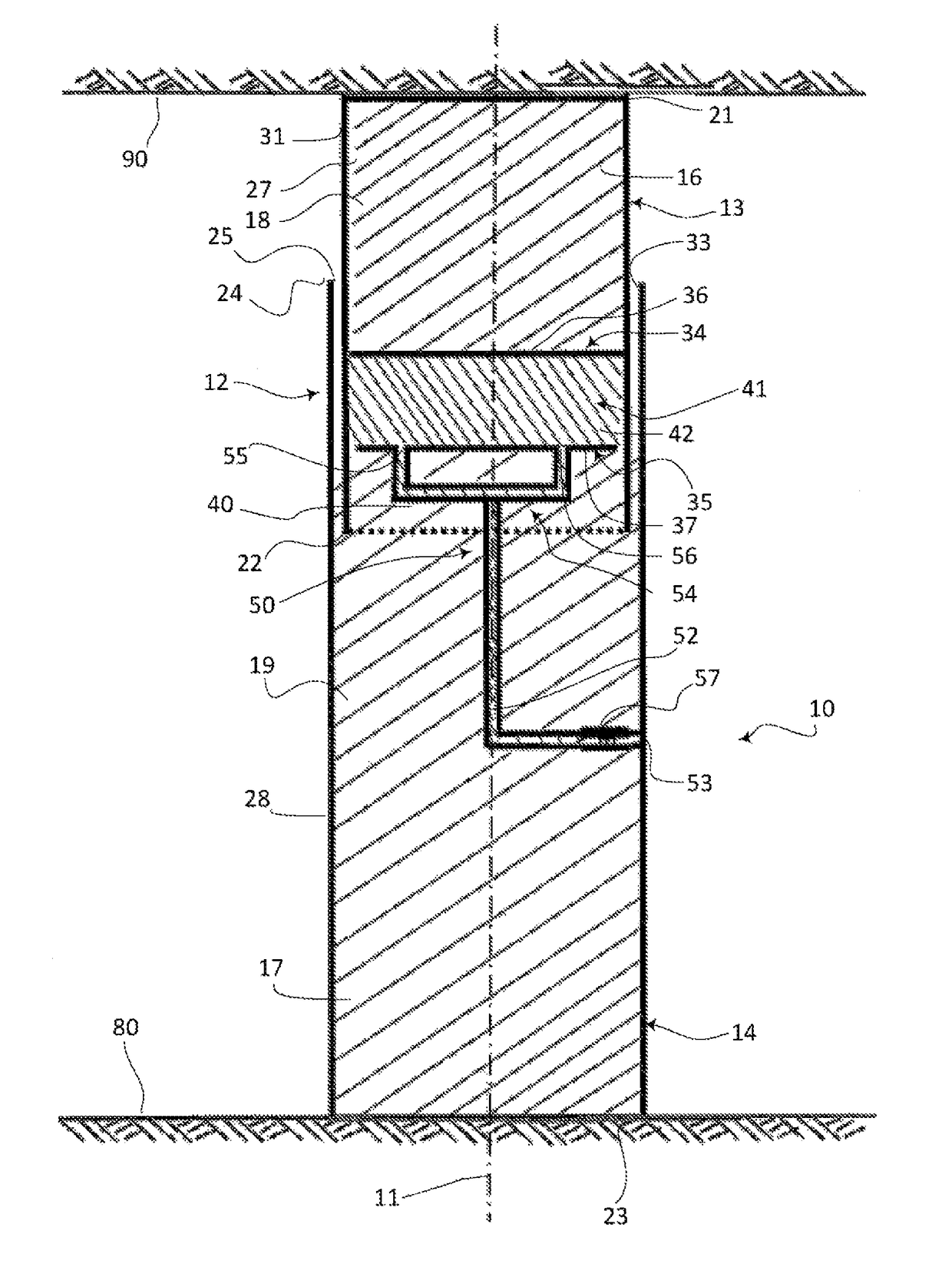
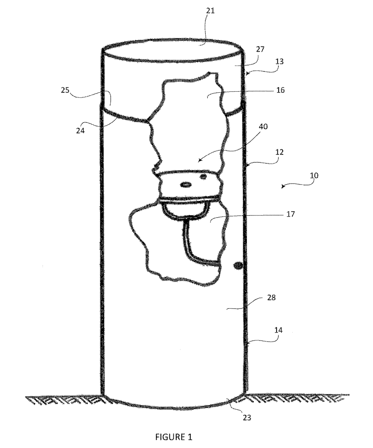
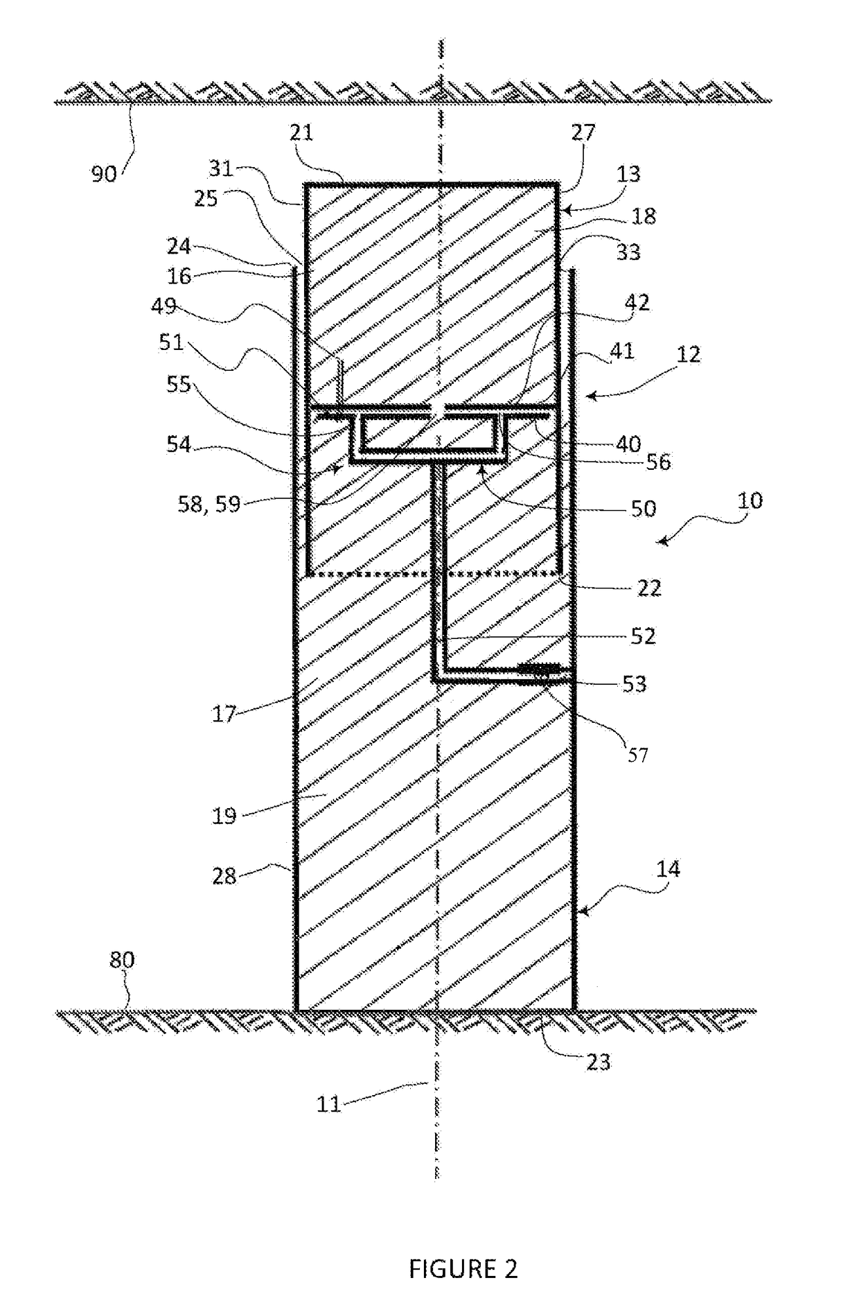
[0024]Referring to the drawings, there is illustrated a support or column 10 having a main axis 11 (FIGS. 2, 3 and 5) for use in a mine tunnel, the support or column 10 comprising an outer casing or shell 12, which includes a first casing part 13 and a second casing part 14. The first casing part 13 is at least partially receivable within the second casing part 14 so as to be capable of slidable movement or axial displacement in the direction of the column axis 11 from a retracted state or position to an extended state or position. In the retracted state or position the overall length of the support or column is less than when in the extended state or position. Each casing part 13 and 14 has a cavity 16 and 17 therein for receiving a core which in the embodiment of FIGS. 1-3 comprises compressible or crushable core sections 18 and 19. The core sections 18 and 19 may be formed in any suitable manner. In one example embodiment, the core comprises an aerated cementitious material such ...


PUM


Abstract

A support comprising an outer casing having a main axis, the outer casing comprising a first casing part and a second casing part, the first casing part being at least partially receivable within the second casing part to enable relative movement therebetween in the axial direction, the casing parts having a cavity therein at least one of which has a core that includes a compressible medium, the support further including a pressure responsive system configured so that under the influence of pressure it can cause the relative displacement or movement between the first and second casing parts.

Description

BACKGROUND[0001]There is a constant danger in underground mining of the collapse of the mine tunnel. Many different arrangements have been proposed to inhibit the collapse of, in particular, the roof of a mine. Support installations for supporting the side walls or roof of an underground mine are often categorized as primary support installations and secondary support installations. Primary support installations are those utilized during the initial excavation of the mine and may, for example, involve the installation of rock bolts into the roof and walls of the mine to stabilize the strata. Secondary support installations are used to provide stability to the strata during and after the mining operations. Examples of secondary support installations include the use of roof bolts, cable bolts or support structures erected within the mine, such structures including beams and support columns, which provide additional structural support to the side walls and roof of the mine tunnel or sh...

Claims


Application Information

Patent Timeline
Patent Type & Authority Patents(United States)
IPC IPC(8): E21D15/44E21D15/14
CPCE21D15/44E21D15/14
Inventor HEALY, IAN EDWARD
Owner BURRELL MINING PRODS
Why Eureka
Try Eureka