Wall-mountable wireless remote control device

a wireless remote control and wall mount technology, applied in the field of remote control devices, can solve the problems of not being able to control the remote control device, not being able to power high-efficiency lamps,

Active Publication Date: 2017-07-04
LUTRON TECH CO LLC
View PDF26 Cites 15 Cited by
  • Summary
  • Abstract
  • Description
  • Claims
  • Application Information

AI Technical Summary

Benefits of technology

[0007]As described herein, a wall-mountable remote control device may be installed in place of an existing light switch and may be configured to transmit wireless signals to an electrical load device to provide control of the electrical load device. The electrical load device may be a controllable light source, such as a screw-in light-emitting diode (LED) or compact fluorescent (CFL) lamp, or a remotely-controllable control module or load control device, such as an LED driver for an external LED light engine. After installation, the remote control device may be easily associated with the electrical load device, such that the electrical load device is then responsive to the wireless signals transmitted by the remote control device. The remote control device may comprise a user interface having one or more buttons (e.g., actuators) and may transmit the wireless signals to the electrical load device in response to actuations of the buttons. For example, the remote control device may comprise a wireless communication circuit, e.g., a radio-frequency (RF) communication circuit configured to transmit an RF signal, and a control circuit coupled to the actuator and the RF communication circuit. The control circuit may be configured to cause the RF communication circuit to transmit the RF signal in response to an actuation of the at least one actuator, where the RF signal includes a command for controlling the electrical load. The electrical load device may be configured to adjust an amount of power consumed by the electrical load device in response to the RF signal (e.g., solely in response to the RF signal). Since the remote control is a “two-wire” device and does not require a neutral connection, the remote control device provides for control of the electrical load device without requiring any additional wiring. Accordingly, the remote control device avoids the problem of the prior art in which an installed light switch may be operated to remove power from a controllable light source, and instead provides one or more buttons to provide for manual control of the controllable light source.
[0008]The remote control device may comprise an air-gap switch adapted to be electrically coupled (e.g., substantially directly electrically coupled) in series between a power source (e.g., an AC power source) and the controllable light source, but may not comprise a bidirectional semiconductor switch (such as a triac or one or more field-effect transistors) for controlling the amount of power delivered to the electrical load device using a phase-control dimming technique (e.g., as in a standard dimmer switch). When the air-gap switch is closed, a load voltage is developed across the controllable light source and is substantially undistorted from the AC line voltage produced by the AC power source. The air-gap switch may be opened to provide an actual air-gap barrier between the power source and the controllable light source to facilitate servicing of the control light source. Since the remote control device does not include a bidirectional semiconductor switch for dimming the electrical load device, an enclosure of the remote control device may be of smaller size than the enclosure of a standard dimmer switch, and thus may be easier to install in an electrical wallbox. The air-gap switch may provide a way of cycling power to the electrical load device to facilitate association of the remote control device and the electrical load device.
[0011]The wireless communication device received on the mounting structure of the air-gap switch device may comprise at least one actuator, a wireless communication circuit configured to transmit a wireless signal, and a control circuit coupled to the actuator and the wireless communication circuit. The control circuit may be configured to cause the wireless communication circuit to transmit the wireless signal in response to an actuation of the at least one actuator, the wireless signal including a command for controlling the electrical load. For example, the wireless communication device may be battery-powered, and may be configured to be removed from the mounting structure after the air-gap switch device is mounted to the wallbox. The control circuit of the wireless communication device may be configured to subsequently cause the wireless communication circuit to transmit the wireless signal in response to an actuation of the at least one actuator when the wireless communication device is removed from the mounting structure. To provide for easy adjustment of the user interface of the remote control device, the wireless communication device may be removed from the mounting structure and replaced with a new wireless communication device having a different number, type, arrangement, or orientation of buttons.

Problems solved by technology

If the light switch is turned off (e.g., opened), the high-efficiency lamp will not be powered and thus will not be able to be controlled by the remote control device.

Method used


Image

  • Wall-mountable wireless remote control device
  • Wall-mountable wireless remote control device
  • Wall-mountable wireless remote control device

Examples


Embodiment Construction

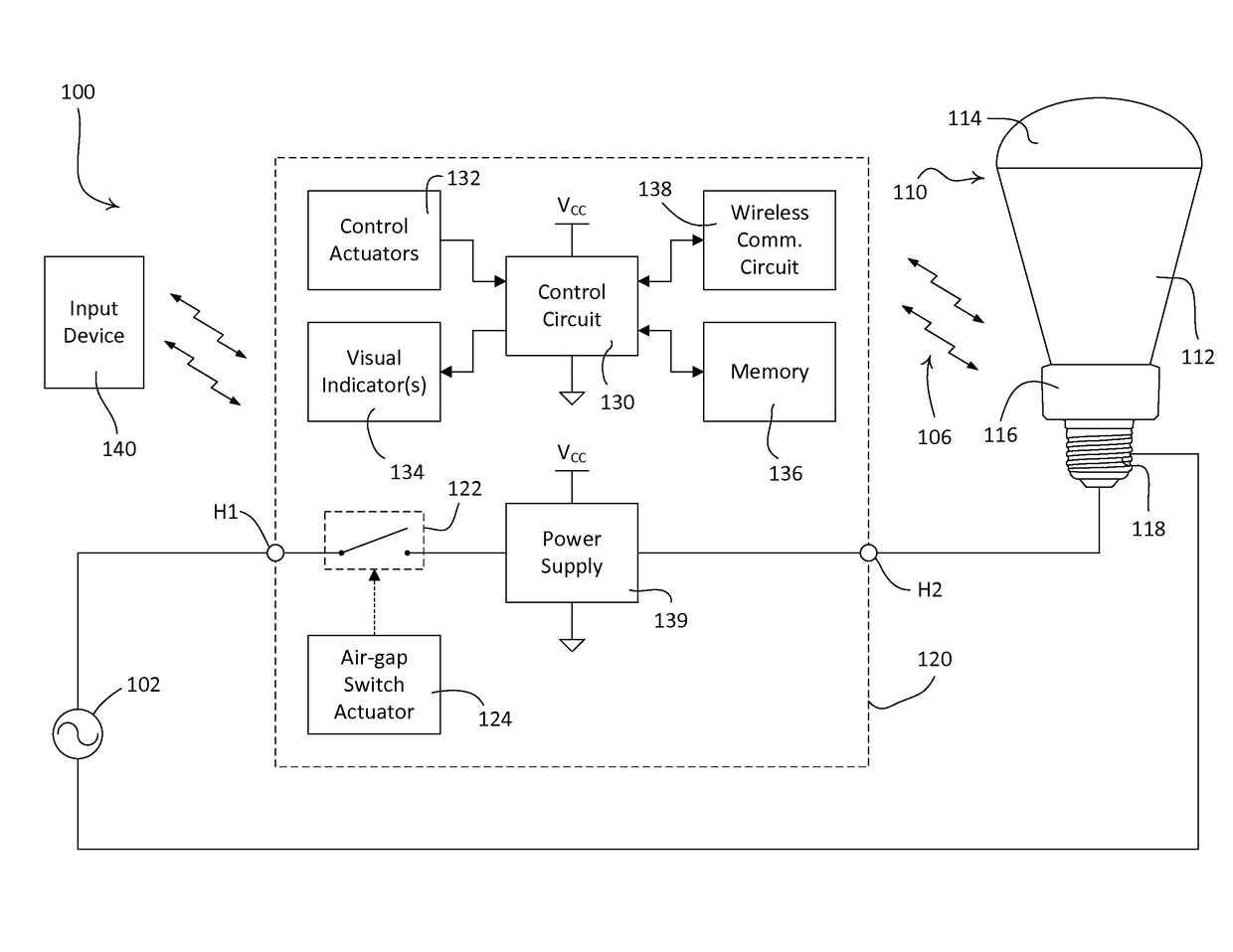
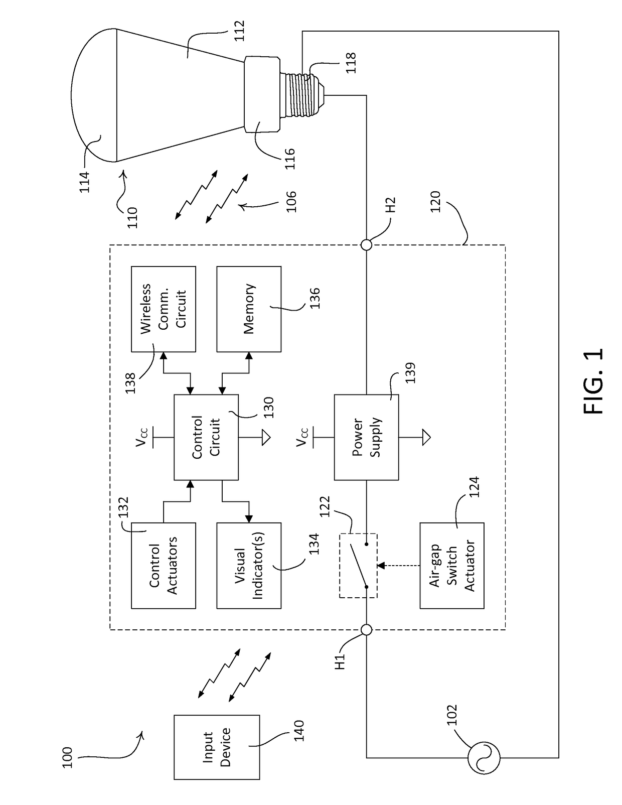
[0021]FIG. 1 is a simple diagram of an example load control system 100 (e.g., a lighting control system) having an electrical load device (e.g., a controllable light source 110) and a remote control device 120. For example, the controllable light source 110 may be a screw-in light-emitting diode (LED) or compact fluorescent (CFL) lamp. The controllable light source 110 may replace a previously-installed light bulb installed in, for example, a ceiling-mounted or wall-mounted lighting fixture (such as a downlight fixture or a sconce) or a lamp (such as a table lamp or a floor lamp). The remote control device 120 is adapted to be coupled in series electrical connection between a power source, e.g., an alternating-current (AC) power source 102, and the controllable light source 110. The remote control device 120 may be installed in an electrical wallbox in place of a standard wall-mounted mechanical switch (e.g., a “toggle switch” or a “light switch”) that was used to turn the previousl...


PUM


Abstract

A wall-mountable remote control device may be installed in place of an existing light switch and may be configured to transmit wireless signals to an electrical load device, such as a screw-in light-emitting diode (LED) lamp, to provide control of the electrical load device. The remote control device may comprise an air-gap switch adapted to be electrically coupled in series between a power source and the controllable light source, but may not comprise a bidirectional semiconductor switch for controlling the amount of power delivered to the electrical load device using a phase-control dimming technique. The remote control device may have a low-profile enclosure that is smaller than an enclosure of a standard dimmer switch, and thus may be easier to install in an electrical wallbox. The remote control device may comprise two parts including an air-gap switch device and a wireless communication device mounted to the air-gap switch device.

Description

CROSS-REFERENCE TO RELATED APPLICATIONS[0001]This application claims priority to commonly-assigned U.S. Provisional Application No. 61 / 921,100, filed Dec. 27, 2013, entitled REMOTE CONTROL DEVICE FOR A CONTROLLABLE LIGHT SOURCE, and U.S. Provisional Application No. 62 / 095,304, filed Dec. 22, 2014, entitled WALL-MOUNTABLE WIRELESS REMOTE CONTROL DEVICE, the entire disclosure of which is hereby incorporated by reference.BACKGROUND[0002]Field of the Disclosure[0003]The present disclosure relates to a remote control device for an electrical load device, and more particularly, to a remote control device adapted to replace a light switch for controlling an electrical load device, such as a controllable light source or a remotely-located load control device for controlling the amount of power delivered to an electrical load.[0004]Description of the Related Art[0005]In order to reduce energy consumption, the use of high-efficiency light sources (e.g., gas discharge lamps, such as compact fl...

Claims


Application Information

Patent Timeline
Patent Type & Authority Patents(United States)
IPC IPC(8): H05B37/02H05B33/08H05B44/00
CPCH05B37/0272H05B33/0845H05B45/10H05B47/19H05B47/115H05B47/195Y02B20/40
Inventor SPIRA, JOEL S.
Owner LUTRON TECH CO LLC
Why Eureka
Try Eureka