Pressure control for hydraulically actuated agricultural headers

a hydraulic actuator and header technology, applied in the direction of fluid couplings, couplings, mechanical devices, etc., can solve the problems of unfavorable hydraulic control of hydraulic actuators

Active Publication Date: 2017-08-01
DEERE & CO
View PDF2 Cites 9 Cited by
  • Summary
  • Abstract
  • Description
  • Claims
  • Application Information

AI Technical Summary

Problems solved by technology

Known hydraulic systems for lifting, floating or tilting the header, however, may tend to remain somewhat pressurized even when the header appears to have been fully lowered to the ground.
This trapped pressure may result in undesirable movement, or resistance to movement, of the header or of other components of the vehicle during maintenance of the header (or other operations).

Method used


Image

  • Pressure control for hydraulically actuated agricultural headers
  • Pressure control for hydraulically actuated agricultural headers
  • Pressure control for hydraulically actuated agricultural headers

Examples


Embodiment Construction

[0019]The following describes one or more example embodiments of the disclosed pressure control system, as shown in the accompanying figures of the drawings described briefly above. Various modifications to the example embodiments may be contemplated by one of skill in the art.

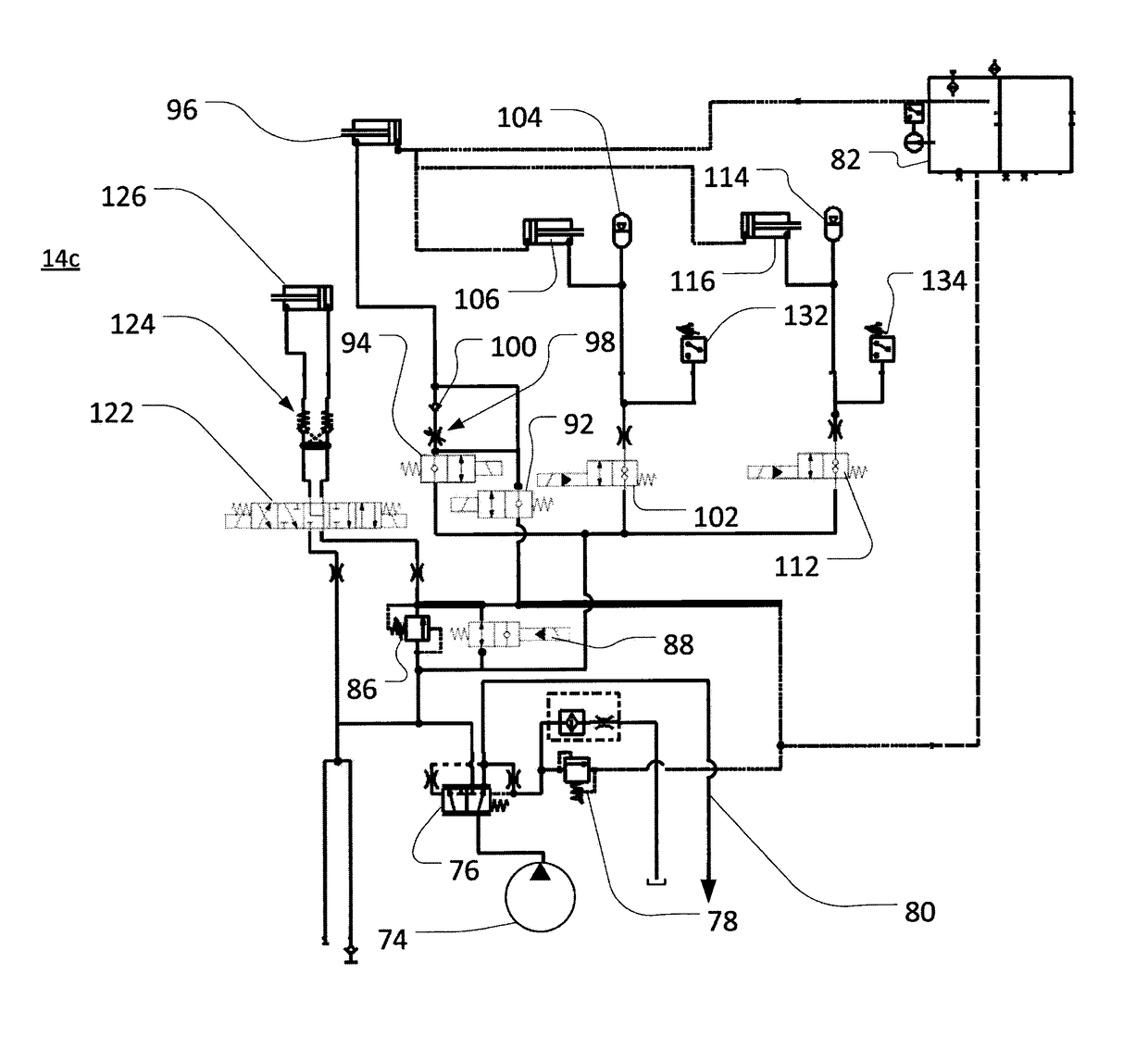
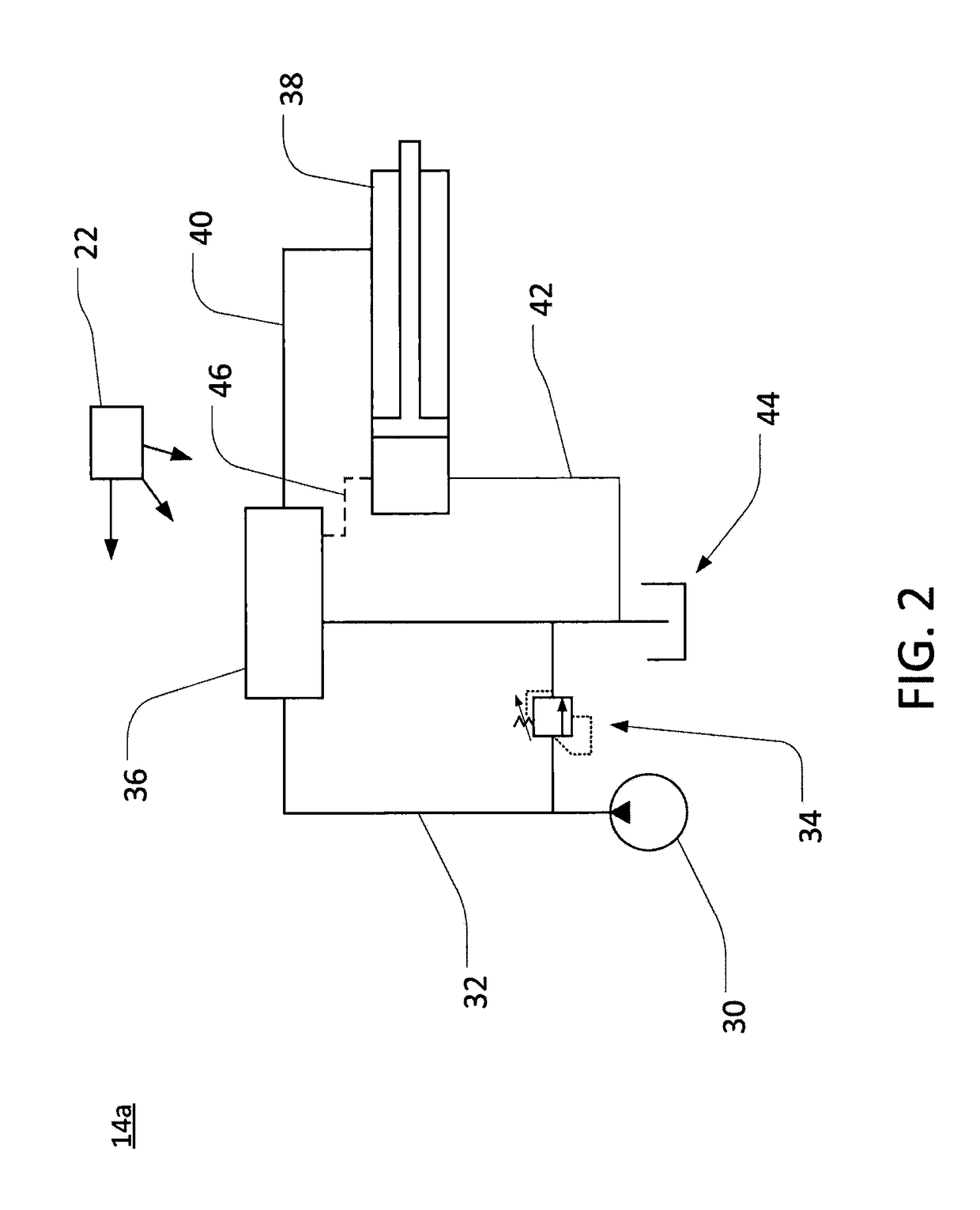
[0020]As also noted above, known agricultural vehicles may utilize various hydraulic systems (e.g., various hydraulic cylinders included in various hydraulic circuits) to control movement of headers supported by the vehicles. In certain embodiments, a hydraulic lifting circuit with a hydraulic cylinder may be provided for raising or lowering a header. In certain embodiments, a hydraulic float circuit may also be provided for floating the header with respect to the ground (e.g., to maintain appropriate ground clearance or to avoid damage to the header from impacts with the ground or other objects). For example, a float circuit may include a hydraulic accumulator (or similar device) in communication with a hydra...


PUM


Abstract

A pressure control system is described for a vehicle having a hydraulically actuated header. The system may include a hydraulic lifting circuit for raising and lowering the header, a hydraulic float circuit for floating the header, and a drain tank. A lifting circuit control valve may be configured to control drainage of hydraulic fluid from the hydraulic lifting circuit to the drain tank. A float circuit control valve may be configured to control drainage of hydraulic fluid from the hydraulic float circuit to the drain tank. A user interface may be configured to receive one or more inputs to control drainage of hydraulic fluid from the hydraulic circuits. Based upon the one or more inputs, at least one of the control valves may be opened, in order to depressurize, respectively, one of the hydraulic circuits.

Description

CROSS-REFERENCE TO RELATED APPLICATION(S)[0001]Not applicable.STATEMENT OF FEDERALLY SPONSORED RESEARCH OR DEVELOPMENT[0002]Not applicable.FIELD OF THE DISCLOSURE[0003]This disclosure relates to the steering of vehicles, including vehicles with caster-mounted rear wheels.BACKGROUND OF THE DISCLOSURE[0004]Various agricultural vehicles are configured to support a header for cutting, gathering, or otherwise processing crop material. For example, agricultural windrowers may be configured to support various headers configured to cut crop material from the ground and arrange the cut material in windrows for later processing (e.g., by a separate baler). As another example, agricultural combines may be configured to support various headers configured to cut crop material from the ground and move the cut material into the body of the combine for further processing (e.g., threshing and winnowing).[0005]In order to raise, lower, and otherwise move or support an attached header, various agricul...

Claims


Application Information

Patent Timeline
Patent Type & Authority Patents(United States)
IPC IPC(8): F16D31/02F15B21/00A01D41/14F15B21/08
CPCA01D41/145F15B21/005F15B21/087F15B21/08
Inventor TEACH, KYLE R.NICHOLS, THOMAS A.ROTOLE, DAVID V.WRIGHT, WALTER C.
Owner DEERE & CO
Why Eureka
Try Eureka